


86
Chapter 6: Replacing Assemblies
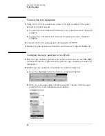
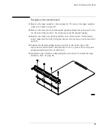
To install the logic analyzer cable
1
Connect the logic analyzer cable to the logic analyzer circuit board.
a
Align the logic analyzer cable end connector with the circuit board
cable connector and gently apply pressure to seat the logic analyzer
cable onto the circuit board connector.
2
Secure the cable to the rear panel.
a
Install the T10 screws (two per cable) and tighten to 5 in/lb.
CAUTION:
If you over tighten the screws, damage to the rear panel may occur. Tighten the screws
only enough to hold the cable in place, approximately 5 in/lb.
Summary of Contents for 16900 Series
Page 3: ...3 Chapter The 16910A Logic Analyzer The 16911A Logic Analyzer...
Page 8: ...8 Contents...
Page 14: ...14 Chapter 1 General Information...
Page 18: ...18 Chapter 2 Preparing for Use...
Page 61: ...61 4 Calibrating This chapter gives you instructions for calibrating the logic analyzer...
Page 65: ...65 Chapter 5 Troubleshooting Troubleshooting Flowchart 1...
Page 66: ...66 Chapter 5 Troubleshooting Troubleshooting Flowchart 2...
Page 82: ...82 Chapter 5 Troubleshooting To test the cables 18 Return to the troubleshooting flow chart...
Page 94: ...94 Chapter 7 Replaceable Parts 16910A Exploded View Exploded view of the 16910A logic analyzer...
Page 95: ...95 Chapter 7 Replaceable Parts 16911A Exploded View Exploded view of the 16911A logic analyzer...
Page 96: ...96 Chapter 7 Replaceable Parts...
Page 102: ...102 Index...


