GPIB Test
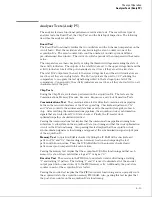
The GPIB test performs a write/read operation to each of the registers of the GPIB IC. A test
pattern is written to each register in the GPIB IC. The pattern is then read and compared
with a known value. The GPIB test will return a valid "Pass" or "Fail" status even if option 020
is not installed.
Passing the GPIB test implies that the read/write registers in the GPIB IC can store a logical
"1" or a logical "0," and that the GPIB IC is functioning properly. Incoming and outgoing GPIB
information will not be corrupted by the GPIB IC.
RS-232C Test
This test checks the basic interface functions of the RS-232C port. Both internal and external
portions of the port circuitry are tested. In order for the RS-232C test to pass, option 020
must be installed and the RS-232C loopback connector must be installed on the RS-232C
connector.
HIL Test
The HIL test exercises both the HIL circuitry internal to the logic analyzer and the HIL
interface between the logic analyzer and external keyboard, if an external keyboard is
connected. First, a read/write operation is performed to each of the registers of the HIL IC. A
test pattern is written to each memory location, read, and compared with a known value.
Second, if an external keyboard is connected to the HIL port, the keyboard controller that
resides in the keyboard is polled by the microprocessor. A test pattern is sent to the keyboard
controller and returned to the microprocessor by the keyboard controller. The test pattern is
then compared with a known value.
Passing the HIL test implies that the read/write registers in the HIL IC can store a logical "1" or
a logical "0," and that the HIL IC is functioning properly. Also, passing the HIL test implies
that the HIL pathway to the external keyboard is functioning and that the keyboard controller
can communicate with the microprocessor in the logic analyzer. Incoming HIL information
from the external keyboard will not be corrupted by the pathway between the keyboard
controller and microprocessor.
Disk Test
The disk test exercises the disk controller circuitry by performing a read/write on a disk.
Either an LIF formatted disk with 20 sectors available space or a DOS formatted disk with 5K
available space is required and should be inserted in the disk drive. When the disk test is
executed, the disk is checked sector by sector to find any bad sectors. If no bad sectors are
found, a test file is created on the disk and test data is written to the file. Then, the file is
read and the test data is compared with known values. At the conclusion of the test, the test
file is erased.
Passing the disk test implies that the disk controller circuitry in the logic analyzer and the disk
read/write circuitry in the disk drive are functioning properly. The disk drive can read and
write to a LIF or DOS formatted disk, and the data will not be corrupted by the disk drive
circuitry.
Theory of Operation
System Tests (System PV)
8–11
Summary of Contents for 1664A
Page 3: ...The Agilent Technologies 1664A Logic Analyzer iii...
Page 8: ...Contents viii...
Page 22: ...2 6...
Page 91: ...Troubleshooting Flowchart 1 Troubleshooting To use the flowcharts 5 3...
Page 92: ...Troubleshooting Flowchart 2 Troubleshooting To use the flowcharts 5 4...
Page 93: ...Troubleshooting Flowchart 3 Troubleshooting To use the flowcharts 5 5...
Page 94: ...Troubleshooting Flowchart 4 Troubleshooting To use the flowcharts 5 6...
Page 95: ...Troubleshooting Flowchart 5 Troubleshooting To use the flowcharts 5 7...
Page 96: ...Troubleshooting Flowchart 6 Troubleshooting To use the flowcharts 5 8...
Page 97: ...Troubleshooting Flowchart 7 Troubleshooting To use the flowcharts 5 9...
Page 98: ...Troubleshooting Flowchart 8 Troubleshooting To use the flowcharts 5 10...
Page 99: ...Troubleshooting Flowchart 9 Troubleshooting To use the flowcharts 5 11...
Page 100: ...Troubleshooting Flowchart 10 Troubleshooting To use the flowcharts 5 12...
Page 101: ...Troubleshooting Flowchart 11 Troubleshooting To use the flowcharts 5 13...
Page 102: ...Troubleshooting Flowchart 12 Troubleshooting To use the flowcharts 5 14...
Page 124: ...Exploded View of the 1664A Replacing Assemblies 6 4...
Page 137: ...Exploded View Exploded view of the 1664A logic analyzer Replaceable Parts Exploded View 7 3...
Page 160: ...8 18...
Page 162: ......


