Clock optimization involves using programmable delays on board the IC to position the master
clock transition where valid data is captured. This procedure greatly reduces the effects of
channel-to-channel skew and other propagation delays.
In the timing acquisition mode, an oscillator-driven clock circuit provides a four-phase,
100-MHz clock signal to each of the acquisition ICs. For high speed timing acquisition
(100 MHz and faster), the sample period is determined by the four-phase, 100-MHz clock
signal.
For slower sample rates, one of the acquisition ICs divides the 100-MHz clock signal to the
appropriate sample rate. The sample clock is then fed to all acquisition ICs.
Threshold
A precision octal DAC and precision op amp drivers make up the threshold circuit. Each of
the eight channels of the DAC is individually programmable which allows you to set the
thresholds of the individual pods. The 16 data channels and the clock channel of each pod are
all set to the same threshold voltage.
Test and Clock Synchronization Circuit
ECLinPS (TM) ICs are used in the Test and Clock Synchronization Circuit for reliability and
low channel-to-channel skew. Test patterns are generated and sent to the comparators during
software operation verification. The test patterns are propagated across all data and clock
channels and read by the acquisition ASIC to ensure both the data and clock pipelines are
operating correctly.
The Test and Clock Synchronization Circuit also generates a four-phase, 100-MHz
sample/synchronization signal for the acquisition ICs operating in the timing acquisition
mode. The synchronizing signal keeps the internal clocking of the individual acquisition
ASICs locked in step with the other ASICs at fast sample rates. At slower sample rates, one of
the acquisition ICs divides the 100-MHz clock signal to the appropriate sample rate. The slow
speed sample clock is then used by all acquisition ICs.
Theory of Operation
The Logic Acquisition Circuitry
8–8
Summary of Contents for 1664A
Page 3: ...The Agilent Technologies 1664A Logic Analyzer iii...
Page 8: ...Contents viii...
Page 22: ...2 6...
Page 91: ...Troubleshooting Flowchart 1 Troubleshooting To use the flowcharts 5 3...
Page 92: ...Troubleshooting Flowchart 2 Troubleshooting To use the flowcharts 5 4...
Page 93: ...Troubleshooting Flowchart 3 Troubleshooting To use the flowcharts 5 5...
Page 94: ...Troubleshooting Flowchart 4 Troubleshooting To use the flowcharts 5 6...
Page 95: ...Troubleshooting Flowchart 5 Troubleshooting To use the flowcharts 5 7...
Page 96: ...Troubleshooting Flowchart 6 Troubleshooting To use the flowcharts 5 8...
Page 97: ...Troubleshooting Flowchart 7 Troubleshooting To use the flowcharts 5 9...
Page 98: ...Troubleshooting Flowchart 8 Troubleshooting To use the flowcharts 5 10...
Page 99: ...Troubleshooting Flowchart 9 Troubleshooting To use the flowcharts 5 11...
Page 100: ...Troubleshooting Flowchart 10 Troubleshooting To use the flowcharts 5 12...
Page 101: ...Troubleshooting Flowchart 11 Troubleshooting To use the flowcharts 5 13...
Page 102: ...Troubleshooting Flowchart 12 Troubleshooting To use the flowcharts 5 14...
Page 124: ...Exploded View of the 1664A Replacing Assemblies 6 4...
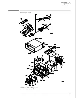
Page 137: ...Exploded View Exploded view of the 1664A logic analyzer Replaceable Parts Exploded View 7 3...
Page 160: ...8 18...
Page 162: ......

