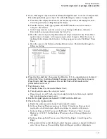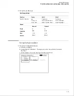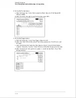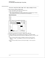
c
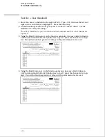
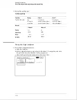
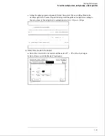
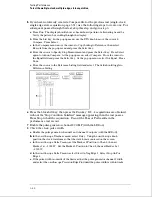
Press the Trigger key. Make sure pattern term
a
is "A". If not, select the field next to
"a" under the label Lab1. Type "A", then press the Select key.
Verify the test signal
1
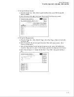
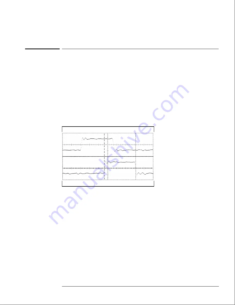
Check the clock pulse width. Using the oscilloscope, verify that the clock pulse
width is 3.50 ns, +0 ps or
−
100 ps.
a
Enable the pulse generator channel 1 and channel 2 outputs.
b
In the oscilloscope Timebase menu, select Delay. Using the oscilloscope knob,
position the clock waveform so that the waveform is centered on the screen.
c
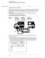
In the oscilloscope Delta V menu, set the Marker 1 Position to Chan 2, then set
Marker 1 at
−
1.3000 V. Set Marker 2 Position to Chan 2, then set Marker 2 at
−
1.3000 V.
d
In the oscilloscope Delta T menu, select Start On Pos Edge 1. Select Stop on Neg
Edge 1.
e
If the pulse width is outside the limits, adjust the pulse generator channel 2 width and
select the oscilloscope Precision Edge Find until the pulse width is within limits.
2
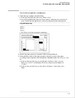
Check the clock period. Using the oscilloscope, verify that the clock period is 20 ns,
+0 ps or
−
250 ps.
a
In the oscilloscope Timebase menu, select Sweep Speed 4.00 ns/div.
b
Select Delay. Using the oscilloscope knob, position the clock waveform so that a
rising edge appears at the left of the display.
Testing Performance
To test the single-clock, single-edge, state acquisition
3–27
Summary of Contents for 1664A
Page 3: ...The Agilent Technologies 1664A Logic Analyzer iii...
Page 8: ...Contents viii...
Page 22: ...2 6...
Page 91: ...Troubleshooting Flowchart 1 Troubleshooting To use the flowcharts 5 3...
Page 92: ...Troubleshooting Flowchart 2 Troubleshooting To use the flowcharts 5 4...
Page 93: ...Troubleshooting Flowchart 3 Troubleshooting To use the flowcharts 5 5...
Page 94: ...Troubleshooting Flowchart 4 Troubleshooting To use the flowcharts 5 6...
Page 95: ...Troubleshooting Flowchart 5 Troubleshooting To use the flowcharts 5 7...
Page 96: ...Troubleshooting Flowchart 6 Troubleshooting To use the flowcharts 5 8...
Page 97: ...Troubleshooting Flowchart 7 Troubleshooting To use the flowcharts 5 9...
Page 98: ...Troubleshooting Flowchart 8 Troubleshooting To use the flowcharts 5 10...
Page 99: ...Troubleshooting Flowchart 9 Troubleshooting To use the flowcharts 5 11...
Page 100: ...Troubleshooting Flowchart 10 Troubleshooting To use the flowcharts 5 12...
Page 101: ...Troubleshooting Flowchart 11 Troubleshooting To use the flowcharts 5 13...
Page 102: ...Troubleshooting Flowchart 12 Troubleshooting To use the flowcharts 5 14...
Page 124: ...Exploded View of the 1664A Replacing Assemblies 6 4...
Page 137: ...Exploded View Exploded view of the 1664A logic analyzer Replaceable Parts Exploded View 7 3...
Page 160: ...8 18...
Page 162: ......


