


Agilent 1260 Infinity II Preparative Autosampler User Manual
185
Maintenance
9
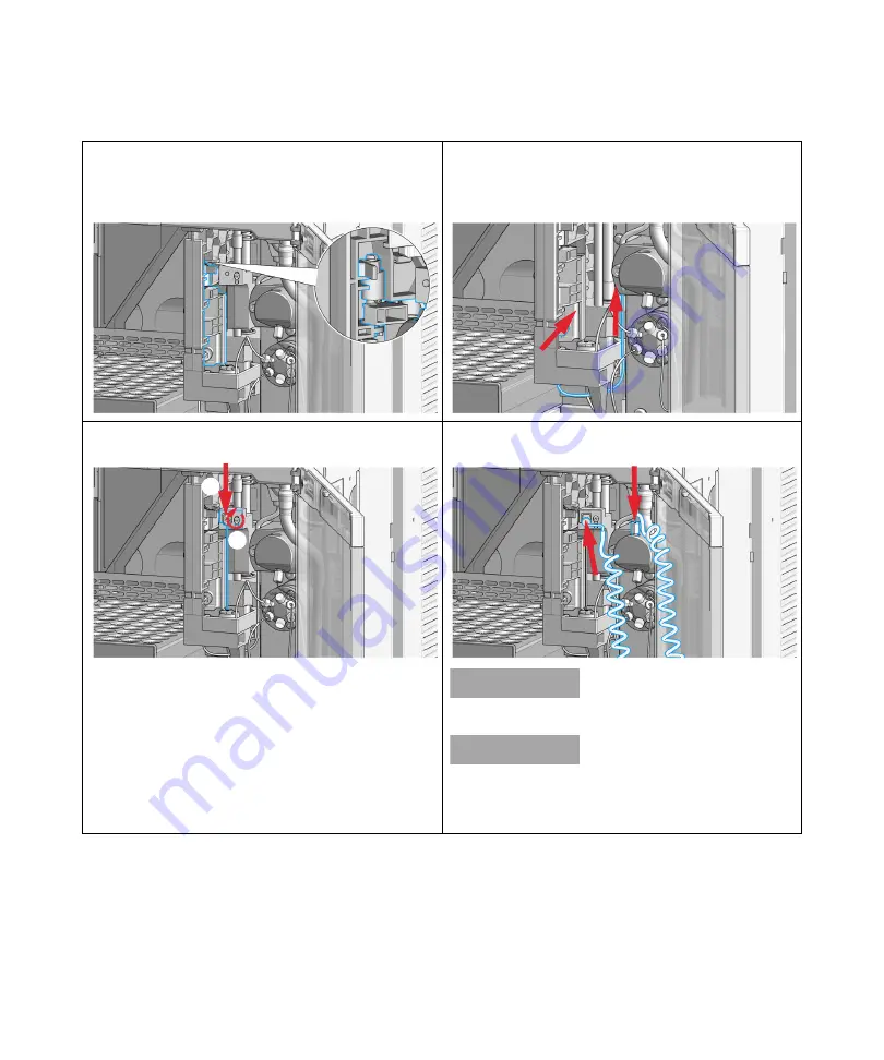
Exchange the Wash Port Assembly
15
Reinstall the new wash port assembly by mounting the
flapper into the housing of the needle station. The pin
must be latched into the housing. Check the movement
of the flapper.
16
Install and reconnect the wash tubing to the peristaltic
pump.
17
Insert the needle (1). Align the needle in the seat, then
tighten the screw firmly (2).
18
Reconnect the sample-loop to the needle.
N O T E
Do not overtighten the fitting!
N O T E
Incorrect positioning and installation of the
needle/loop connection can result in damaging and
breaking the sample loop.
1
2


