background image


58


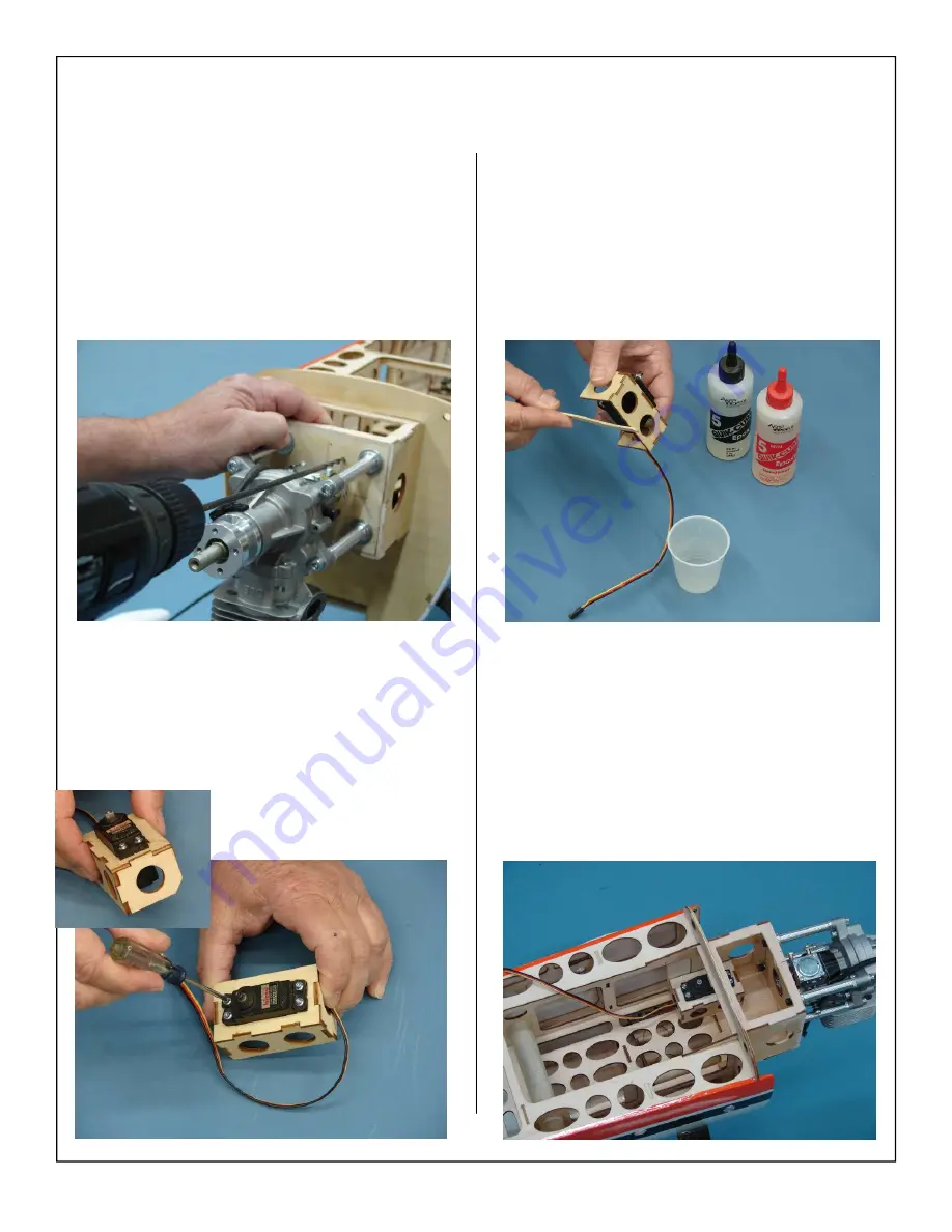
3.  Use a drill bit to drill the holes for the throttle 

pushrod.  

4.  Install the throttle servo in the preassembled la-

ser cut mounting tray as shown below.  


Note: 

It may be necessary to remove the bottom  


 corner of the servo mounting tray as shown. 


 This will allow the mounting tray to fit over 


 the reinforcement tri-stock.   

5.  Apply 5 minute epoxy to the side of the servo 

mount that will be in contact with the engine box 
side.   

6.  Install the servo mount to the inside of the en-

gine box as shown.  Use tape or clamps to en-
sure the servo mount does not move until the 
epoxy sets. 

Summary of Contents for 30cc EDGE 540 ARF-QB

Page 1: ...1 30cc EDGE 540 ARF QB Quick Build ASSEMBLY MANUAL AEROWORKS 4903 Nome Street Denver CO 80239 Phone 303 371 4222 Fax 303 371 4320 E mail info aero works net...

Page 2: ...mbly 37 2 Stroke Engine Installation 41 2 Stroke Throttle Servo Installation 45 4 Stroke Engine Installation 48 4 Stroke Throttle Servo Installation 52 Gas Engine Installation 55 Gas Throttle Servo an...

Page 3: ...from defects in both material and workmanship at the date of purchase This warranty does not cover any component parts damaged by use or modification In no case shall Aeroworks liability exceed the or...

Page 4: ...embly of your new 30cc EDGE 540 ARF QB Inventory and inspect all parts and hardware for any imperfections or damage Notify Aeroworks immediately if there are missing or dam aged parts INTENDED USE Thi...

Page 5: ...uselage 4 4 40x16mm hex style bolts for installing the canopy 4 6 bonded washers for the mounting of the canopy 4 3mm split lock washers for the mounting of the canopy 1 3 5 o d x800mm Antenna tube in...

Page 6: ...nd threaded pushrods with nuts for ailerons 2 4 40 4 Left hand and Right hand threaded pushrods with nuts for elevators 1 Wrench for the left hand and right hand threaded pushrod 8 Brass spacers 2 for...

Page 7: ...k 8 x11 for making the template for cutting of cowling 1 Paper Degree Meter for the Rudder Small 1 12mm Aluminum Insert 6 Rubber Grommets each for 6mm 8mm 10mm Fuel line and wire guide 11 1 C G Buddy...

Page 8: ...1 60 FX 1 Bisson Pitts Muffler 1 18x6 Propeller 1 Glow Fuel Filter Engine Option 3 Glow 4 Stroke 1 Saito 1 80 1 Stock Saito 1 80 Muffler 1 18x6 Propeller 1 Glow Fuel Filter Motor Options 4 Electric 1...

Page 9: ...lying These servos will provide the best perform ance possible Note Servos available through Aeroworks 5 Hitec 7985 Servos for flight surfaces 1 Hitec 635HB Servo for throttle Recommended Spinner 1 2...

Page 10: ...Switch HD w Deans Ignition Power System If using the DLE 30 or any other gas engine the Aeroworks Ignition Power System is recommended 1 Fromeco 2600mah Li Ion Battery w Universal Connector 1 Smart Fl...

Page 11: ...ring sock Masking tape Modeling knife Needle nose pliers or crimping tool Paper towels Pen pencil or felt tipped marker Phillips screwdriver Rubbing alcohol Ruler and tape measure Scissors T pins Waxe...

Page 12: ...ng you will be re warded with a long lasting beautifully covered model TIGHTENING AND RE SHRINKING THE COVERING 2 Using your covering iron with a soft sock gently apply pressure and rub in the coverin...

Page 13: ...13 1 Your model is covered with Ultracote covering In case of repairs the colors are Orange Black Scheme Orange 877 Pearl Charcoal 846 White 870 Ultracote Colors...

Page 14: ...Cut strips of clear covering to fit the hinge gaps Use covering iron to seal the clear covering snugly into the bottom of the hinge lines as shown for air tight hinge seals IMPORTANT It is the respon...

Page 15: ...l the hinges have cooled down and the glue has re hardened 3 If the elevator hinges are tight follow the same process as described for the wings Note Once these steps have been completed the hinges wi...

Page 16: ...bly see glue on all glue joints it is still recommended that the joints be reglued Due to changes in humidity during the life of the aircraft glue joints can separate it is always recommended that the...

Page 17: ...the wing to test fit the in stallation and ensure servo lead is the correct length Note 165 in oz digital metal geared servos are recommended Servo selection can be the difference between a great fly...

Page 18: ...ll with the output arm toward the leading edge of the wing Mark and drill location of servo mounting holes 7 Install servo with servo mounting screws Pushrod Control Horn Installation 1 Gather the ail...

Page 19: ...k to servo arm shown below Note Flat washer will prevent ball link from coming loose from brass ball 4 Place the control horns over the predrilled mounting holes 5 Use a drop of thick CA glue on each...

Page 20: ...the aileron hinge line and the trailing edge of the aileron is even with the trailing edge of the wing in the neutral position Note Control horns have been set at a slight offset to provide full powe...

Page 21: ...o does not bind at either end point at full deflection A 1 servo arm is rec ommended for best results A 1 1 4 servo arm is required for full deflection of the aileron bevel 11 Repeat all the above ste...

Page 22: ...24 servo extension 1 Aeroworks Safety Clip Note 24 servo extension will be used to connect servos to receiver during a later step STAB AND ELEVATOR ASSEMBLY 2 Attach the 24 extension to the servo lea...

Page 23: ...llation of ball link to servo arm shown below Note Flat washer will prevent ball link from coming loose from brass ball Pushrods have both left and right hand threads This allows for easier fine adjus...

Page 24: ...rom loosening due to vibration as shown 6 Mount the control horn using six wood screws Note CA glues have a fast drying time Remember to work quickly 7 Use the supplied adjustment wrench to adjust the...

Page 25: ...25 9 Finished elevator servo installation shown be low...

Page 26: ...o the hinge joint This ensures no epoxy gets into the hinge during assembly 3 Mix epoxy in mixing cup and use a tapered stick to apply the epoxy inside the pre drilled holes in the trailing edge of th...

Page 27: ...epoxy with alcohol wetted wipes 7 Ensure there is no gap between fin and rudder Allow epoxy to fully cure Check you have full rudder deflection before epoxy fully cures Rudder Horn Pull Pull Cable an...

Page 28: ...control horn The ball link may be moved up or down for more or less control throw 3 Thread brass coupler half way into ball link Note There are two types of 4 40 couplers supplied 2 are for the throt...

Page 29: ...erence between a great flying model and a model that will crash Always use brand name high quality servos 9 Install the rudder servo in the servo cutout with the output shaft to the front Note Remove...

Page 30: ...fuse and do not cross each other 12 Using an X ACTO knife clean away any burrs from brass swags This will allow the rudder cable to pass through brass swage easily 13 Thread cable through brass swage...

Page 31: ...back through the brass swage tube and pull tight 16 Crimp the brass swage tube with a crimping tool or pliers 17 Cut off excess cable as shown 18 A drop of thin CA may be applied to the swage tube to...

Page 32: ...to center rudder servo Ensure servo trim and sub trims are centered Note On metal geared servos use blue Loctite for all Servo arm mounting screws 21 Tape the rudder balance tab to the top leading edg...

Page 33: ...mbly 3 Tail wheel mounting screws 1 Steering tiller 2 Tiller mounting screws 2 Steering springs Note Aftermarket carbon tail wheel shown your kit includes the aluminum tail wheel assembly Installation...

Page 34: ...the tail wheel with pre drilled mounting holes on the bottom of the fuse 6 Place a drop of thick CA on tail wheel strut mounting screws before inserting in the pre drilled mounting holes on the bottom...

Page 35: ...ween both tail wheel and steering tillers 9 Use pliers to twist spring end closed around the rudder steering tiller 10 With spring centered between tiller arms and tail wheel centered bend spring wire...

Page 36: ...36 12 Repeat spring installation for other side...

Page 37: ...gear bolts with lock washer and flat washer Use a drop of blue Loc tite on landing gear bolts before attaching the landing gear 5 Bolt landing gear strut to fuse with 4 8 32 bolts and washers Mountin...

Page 38: ...of the axle bolt vertical and snug the lock nut against the landing gear strut Note Do not tighten securely yet Align axle bolt with front of gear 9 Align the wheel pant slot over the axle bolt as sho...

Page 39: ...set screw and tighten the wheel collar in place 12 Install the wheel and outer wheel collar Use blue Loctite on the wheel collar set screw before final tightening 13 Final installation of wheel pant...

Page 40: ...40 14 Repeat above steps for other wheel and wheel pant 15 Final landing gear installation shown below...

Page 41: ...ce of engine the installation may differ slightly 2 STROKE ENGINE INSTALLATION 2 Align cowl to fuse and bolt in place Mark the location of the air exit from the fuse onto the cowling This step will he...

Page 42: ...gine mounting holes 6 Use a 8 32 bolt along with a large fender washer to install the blind nuts as shown below 7 Tighten the bolt until the blind nut is fully seated in the firewall Note Use thick CA...

Page 43: ...flat washers mount engine mount to firewall Tighten the bolts evenly to prevent crushing of the firewall 12 Set the engine in between the left and right mounting rails It will be necessary to clamp t...

Page 44: ...or pen Ensure the mark is in the center of the engine mounting hole Note We recommend the Great Planes Dead Center Engine Mount Hole Locator Part GPMR8130 15 Use a drill bit to drill the engine mount...

Page 45: ...od guide tube 1 Throttle pushrod 1 Mounting tray 2 Mark the location of the throttle pushrod guide tube on the firewall as shown 3 Remove the engine and use a drill bit to drill the holes for the thro...

Page 46: ...servo mount that will be in contact with the engine box side 7 Install the servo mount to the inside of the en gine box as shown Use tape or clamps to en sure the servo mount does not move until the...

Page 47: ...nylon clevis to the carburetor as shown Use a piece of fuel tubing around the clevis to prevent it from coming undone in flight 10 Install the pitts muffler at this time 2 stroke en gine installation...

Page 48: ...he installation may differ slightly 4 STROKE ENGINE INSTALLATION 2 Align cowl to fuse and bolt in place Mark the location of the air exit from the fuse onto the cowling This step will help with the pr...

Page 49: ...gine mounting holes 6 Use a 8 32 bolt along with a large fender washer to install the blind nuts as shown below 7 Tighten the bolt until the blind nut is fully seated in the firewall Note Use thick CA...

Page 50: ...ne in between the left and right mounting rails It will be necessary to clamp the motor in place for the next few steps 12 Adjust the motors position until the thrust washer is 6 1 2 away from the fir...

Page 51: ...the center of the engine mounting hole Note We recommend the Great Planes Dead Center Engine Mount Hole Locator Part GPMR8130 14 Use a drill bit to drill the engine mounting holes into the engine moun...

Page 52: ...be 1 Throttle pushrod 1 Servo Tray 1 Plastic pushrod keeper 2 Mark the location of the throttle pushrod guide tube on the firewall as shown 3 Remove the engine and use a drill bit to drill the holes f...

Page 53: ...servo mount that will be in contact with the engine box side 7 Install the servo mount to the inside of the en gine box as shown Use tape or clamps to en sure the servo mount does not move until the...

Page 54: ...xcess guide tube as shown below 10 Mark the position where the Z Bend will be lo cated on the throttle pushrod as shown 11 Create a Z Bend in the throttle pushrod and in stall onto carburetor arm 4 St...

Page 55: ...r alignment of the template material during the cowl instal lation steps shown later in this manual Engine Installation 1 The 30cc Edge 540 will accept a wide range of engine types The DLE 30 rear car...

Page 56: ...the engine mounting holes 6 Using mounting bolts and flat fender washers mount engine to firewall 7 Use blue loctite to secure the engine mounting bolts in place This will insure that the mounting bo...

Page 57: ...Throttle Servo and Choke Installation 1 Gather the following items for the throttle servo installation 1 Throttle servo with mounting screws 1 3 4 servo arm 1 Servo mount 1 4 40 metal rod threaded at...

Page 58: ...move the bottom corner of the servo mounting tray as shown This will allow the mounting tray to fit over the reinforcement tri stock 5 Apply 5 minute epoxy to the side of the servo mount that will be...

Page 59: ...rass spacer to the servo arm as shown below 10 With servo arm still 90 degrees to servo and throttle arm of carburetor in the center or half throttle position Mark the cut location for the throttle pu...

Page 60: ...ushrod to length 12 Gather the soldering tools as shown below Note For best results we recommend a high quality Silver Solder like Sta Brite silver solder 13 Lightly sand end of pushrod for best bond...

Page 61: ...1 4 40 metal rod threaded at one end 1 4 40 ball link assembly with hardware 1 4 40 Threaded insert 1 Large Zip Tie 2 Small Zip Ties 3 Location of manual choke pushrod shown be low 2 We recommend ins...

Page 62: ...ignition module on the side of the engine mounting box and mark the location of the nylon tie holes as shown 3 Use a 1 4 bit to drill the ignition module mounting holes 4 Mount the engine ignition mo...

Page 63: ...plate for a template Using a modeling knife cut out the switch hole Note Ensure switch location does not interfere with the mounting of the wing 7 Mount switch in accordance with the switch manufactu...

Page 64: ...as shown below Use Zip ties to secure the pick up line to the tubing as well as to the clunk 3 Finished stopper shown below Note Fill line will also be used to defuel tank lifting tail as high as pos...

Page 65: ...vibration 7 Install the tank Run the fuel pick up line to the engine Secure the tank with the two long nylon ties trim away any excess nylon tie as shown 8 Gather the fuel filler dot and drill bits a...

Page 66: ...66 9 Mark location of fuel filler dot 10 Drill hole to accommodate fuel filler dot 11 Use thick CA to secure fuel dot in fuse 12 Feed filler line through dot and plug line into filler plug as shown...

Page 67: ...67 13 For four stroke engines route fuel line above the carb inlet to keep the motor from flooding 14 Secure fuel pick up line to engine carburetor with small nylon tie...

Page 68: ...pplied FUEL TANK ASSEMBLY AND INSTALLATION FOR GAS ENGINE 2 Locate the 2 supplied brass fuel barbs Solder a brass fuel barb to the fuel line pick up tube This will keep the weight of the fuel clunk fr...

Page 69: ...t tube into rubber stopper and bend upward Note No brass barbs are required for the air vent tube 7 Install the fuel tubing and clunk Secure the fuel tubing with nylon ties to the pick up tube and clu...

Page 70: ...n ties Note The fuel T and fuel filter are not supplied but are available through Aeroworks 2 Install a short piece of fuel line and the fuel T to the fuel pick up tube Note Using a heat gun to soften...

Page 71: ...off during flight 5 Thread nylon ties under tank mounting plate and center in position 6 Install foam rubber pad for fuel tank to rest on Foam rubber will help prevent fuel from foam ing or getting ai...

Page 72: ...t with a smaller size drill bit then increase the bit size to the correct size to fit your filler dot This will help prevent the fuse side from splitting or cracking 9 Mark location of fuel filler dot...

Page 73: ...tie to the point of closing the vent line This will pre vent the vent line from falling back inside the fuse and flooding the airplane with gas during fueling 14 Secure fuel pick up line to engine ca...

Page 74: ...ue loctite to ensure the muffler mounting bolts do not come loose due to vibration 2 Attach the muffler to the motor at this time Note Muffler will be removed during cowl installa tion It may be left...

Page 75: ...ps RADIO INSTALLATION 2 Mount radio switch in accordance with the switch manufacturers instructions and hardware Note Ensure switch does not interfere with wings or cowl installation 3 Install regulat...

Page 76: ...wrap strap as shown 6 Use tape to secure the receiver antennas inside the fuse 7 Typical radio installation shown for heavier en gine selections Note If models CG is tail heavy move batteries forward...

Page 77: ...Tape template to the fuse Mark the location of the air exit from fuse onto template Note It may be necessary to cut a notch in the template for the muffler 2 Measure 1 4 back from F1 on both sides of...

Page 78: ...t out the template using the line marked in the previous step Use marks made in step 6 to align cut out with air exit on the bottom of the fuse 8 Check the fit of the template at this time It may be n...

Page 79: ...nsfer the location of the cut out onto the cowl 12 Cut out the marked area just like the previous steps 9 Align template with bottom of cowl Use a felt tip marker to transfer the template cutout patte...

Page 80: ...exit from fuse onto template Note It may be necessary to cut a notch in the template for the muffler 2 Measure 1 4 back from F1 on both sides of the air outlet as shown 3 Align template with marks an...

Page 81: ...It may be necessary to make small adjustments to the cutout to get it to fit properly 5 Mark the location of the muffler exits as shown Use a hoppy knife to remove this section of the template 6 Trac...

Page 82: ...tern to the cowl and mark cut location Note Pay close attention to the marker you choose Some permanent markers may not be easily removed Also When using rubbing alcohols or other paint removers alway...

Page 83: ...reat planes large outrunner motor mount 2 Use a covering iron to seal the covering before removing any material 3 Use a sharp X Acto knife to remove the cover ing from the hot air exits 4 Final hot ai...

Page 84: ...s 2 Velcro Straps 1 Foam Pad 6 Use 30 minute epoxy to glue the air inlets in place Use tape to secure the inlets to the motor box while the glue cures 7 Finished air inlet installation shown below 8 T...

Page 85: ...engine mounting holes 11 Use a 8 32 bolt along with a large fender washer to install the blind nuts as shown below 12 Tighten the bolt until the blind nut is fully seated in the firewall Note Use thi...

Page 86: ...away from the firewall 16 Mount the ESC to F1 as shown below Ensure that the speed control will receive plenty of air flow to keep it from overheating 17 Attach the hook side of Velcro to the battery...

Page 87: ...19 Use two One Wrap Velcro Straps to firmly se cure the batteries to the tray Attach straps to the small pieces of Velcro at the fuse sides to help hold the straps in place while batteries are being...

Page 88: ...ide the rubber backed washers on the wing mounting bolts and insert bolts through the fuse side and into the wing root blind nuts Tighten snugly but do not over tighten and crack the fuse or wing root...

Page 89: ...he stab mounting bolts and insert bolts through the stab mounting tabs and into the fuse blind nuts Tighten snugly but do not over tighten and crack the stab mounting tabs or the fuse sides 5 Gather 4...

Page 90: ...the rubber backed washers on the hatch mounting bolts and insert bolts through the hatch mounting holes and into the fuse blind nuts Tighten snugly but do not over tighten and crush the hatch or the...

Page 91: ...ruler scis sors hobby knife plastic squeegee or credit card Windex or Application fluid like Rapid Tac Also a solution of 1 drop of dish detergent to a cup of water sprayed on the model will as sist...

Page 92: ...ecals from the rest of the decal sheet 4 Cut a strip of transfer tape the same size as the decal cut in the previous step 5 Peel the backing from the transfer tape 6 Apply the transfer tape on top of...

Page 93: ...r tape onto the decal 8 Peel the backing away from the decal 9 Spray the area with application fluid before in stalling the decal to allow a longer working time and aid in positioning the decal 10 App...

Page 94: ...ll excess application fluid Let decal set until dry enough to be able to remove transfer tape without removing decal Do not leave until completely dry or transfer tape will be difficult to remove 12 P...

Page 95: ...fuse and install the CG Buddy on the wing tube and front rotation dowel as shown The cable attachment should be on the top side of the wing Make sure the CG Buddy is se curely latched to the wing tub...

Page 96: ...batteries installed and READY TO FLY Try to balance the model by moving the batteries and receiver before adding any ballast IMPORTANT The CG Buddy is not adjustable and is set to bal ance the airplan...

Page 97: ...style in small steps especially when shifting the CG to ward the tail Move the battery or add small stick on weights to the nose or tail as necessary 4 For aerobatic flying a more aft balance point is...

Page 98: ...row in inches 4 Gather the Rudder Throw Meter Supplied and scotch tape 5 Slide the throw meter under the rudder boost tab 6 Center the throw meter on the rudder using the centering marks on the meter...

Page 99: ...the flight control deflection meter not supplied to measure the throws in degrees Prop up the tail of the aircraft until the fuselage is parallel to the table top 10 Use the widest part of the ailero...

Page 100: ...rior to mounting on engine Flight Controls Ensure all flight controls are free from binding and are centered Check that all hinges are tight and will not pull out Control linkages must be rigid and ti...

Page 101: ...you can think of Here is a list of some of the more popular aerobatic and 3D maneuvers you can try Loops and rolls Knife edge flight Stall turns Snap rolls 2 4 and 8 point rolls Slow rolls Spins upri...

Page 102: ...at your flying field Fuel Line Installation Kit The fuel line installation kit includes everything needed to plumb your gasoline powered aircraft 3 feet of 1 8 I D Dubro tygon tubing is pro vided Sim...

Page 103: ...dge 540 Stick Plane The Edge 540 Stick plane is an accurate replica of the 30cc Edge Use this to practice new maneuvers and learn airplane orientation before ever attempting it with the real thing 2 5...

Page 104: ...__ ___________________________________________________________________________ ___________________________________________________________________________ _____________________________________________...

Reviews: