


Information subject to change
12-17-2018
3110 HELP FILES – SECTION 5
24
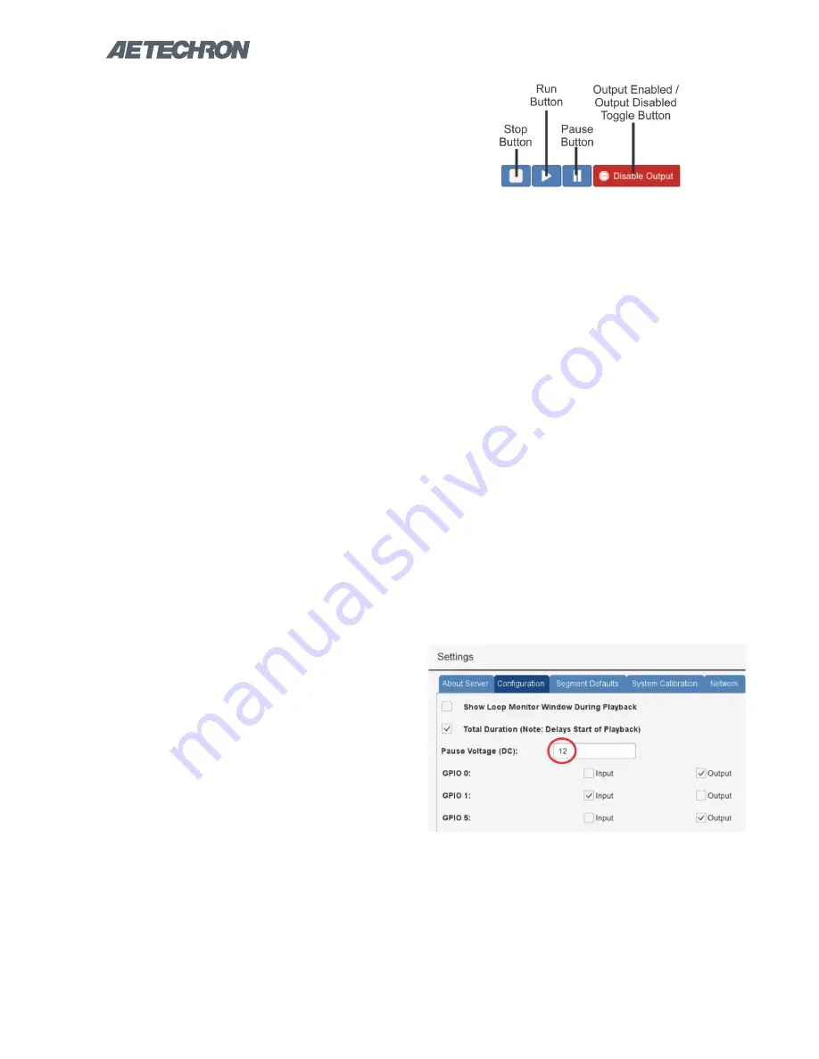
Figure 5.14 – Test Playback and Output Controls
5.3 Running a Test
One or more waveforms and/or controls that have
been added to the active test window can be run
using the controls located below the display win-
dow. See
Figure 5.14.
1. If using the stand-alone 3110, connect the
3110 and amplifier following the instructions in
the section
“Getting Started.”
2. Attach an oscilloscope to the Test Supply or
amplifier Output connectors to monitor the
signal being generated.
3. In the 3110 software interface, use the
Add
Wave
button to add one or more waveforms to
the test window.
4. Press the
Run
button. When the
Run
button
is pressed, the system will begin generat-
ing signal starting at the beginning of the test
sequence (the waveform or control farthest to
the left). The System Status reporting message
will change from “Idle” to “1 of X,” with X being
the total combined number of waveforms and
controls in the test.
5. Notice that individual segments may be high-
lighted in the display window during playback.
This occurs when the 3110/DSR system is
currently generating the highlighted segment
and the segment is equal to or greater than
one second in duration. Segments shorter than
one second are too short to register as being
highlighted.
6. Press the
Pause
button. The system will stop
generating the signal described in the test se-
quences. By default, the controller will gener-
ate no signal while a test is paused. To gener-
ate a predetermined DC signal instead, change
the Pause Voltage setting on the Configuration
tab in the Settings window. See Figure 5.15.
7. Press the
Run
button. The system will begin
generating signal starting at the beginning of
the last active waveform segment. The System
Status reporting message will continue the
count of the number of segments run in the
test.
8. Press the
Stop
button. When the
Stop
button
is pressed, the 3110 will stop signal generation,
and the test will reset to the start of the first
waveform. The system will report its status as
“Idle.” The system will report its status as Idle
at all times that the 3110 is operating normally
but a test is not actively running.
9. Restart the test by pushing the
Run
button,
and then push the red
Output Enabled
but-
ton. The button will change to green and will
be labeled
“Output Disabled.”
Notice that the
test continues to progress in the 3110 display,
but that signal output has been muted.
10. Press the green
Output Disabled
button.
The button will toggle back to the red
“Output
Enabled”
button and signal generation will
resume. Note that running a test with output
disabled can be useful for testing a sequence
before generating output.
5.4 Creating an Exponential Sweep
Figure 5.15 – Setting the Pause Voltage (DC)