background image

7-73 

8. 

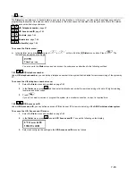
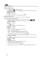
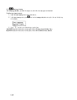
You see the following on the display: 


9. 

For button 3 (small button), you can choose between the following functions: 

™


None:  

The button is not activated (default).


™


Panic: 

The button triggers a panic alarm.


™


Utility Output:

 The button activates a utility output.  

If you select the switch output function and confirm it with 

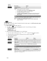
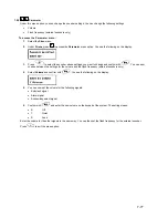
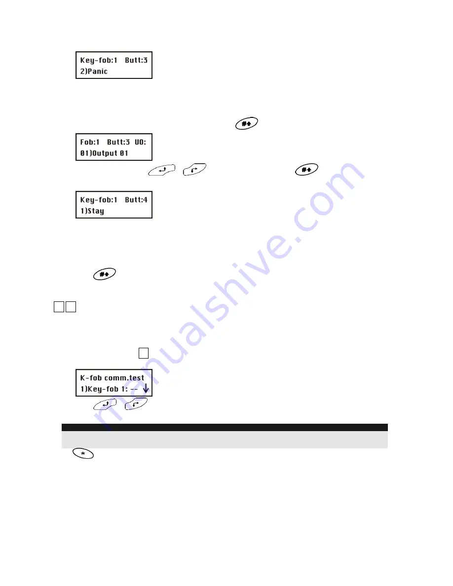
, you see the following on the display: 


Select a utility output with 


or 

 and confirm your selection with 

10. 

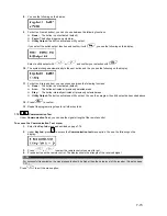
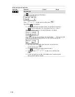
The system changes automatically to the next button and the you see the following on the display: 


11. 

For button 4 (large button), you can choose between the following functions: 

™


None:

   The button is not activated (default). 

™


Arm:

   The button activates all previously selected areas. 

™


Stay:

   The button internally activates all previously selected areas. 

™


Utility Output:

 The button activates a utility output. You can then program the utility output as described above. 

12. 

Press 

 to confirm. 

13. 

Repeat the programming steps for all other key fobs. 

7.7.3 

77


33

 Communication Test 

Under 

Communication Test

, you can see the signal strength of the remote control.  

To access the Communication Test menu: 

1. 

Select the 

Key-fob

 menu as described on page 7-74.


2. 

Under 

Key-fob

, press 

11


to access the 

Communication test

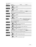
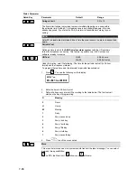
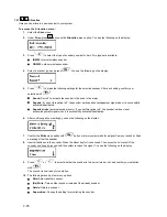
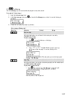
 menu option. You see the following on the 

display:


3. 

Press 


or 

 to select the remote control you want to test. 

4. 

Press a button on the remote control. The display shows the strength of the received signal.  

NOTE: 

For successful transmission, the signal strength should be higher than the noise level of the receiver. (See also page 
7-31.) 

Press 

 to exit the menu option.  


Summary of Contents for WIRELESS ALARM SYSTEM

Page 1: ...contain important installation and operation information Bear this in mind if you pass the product on to others Store these installation instructions in a safe place for future reference For a list of...

Page 2: ...opy microfilm or storage in computer systems require the express written permission of the publisher Reprinting prohibited even in part These operating and installation instructions correspond to the...

Page 3: ...7 5 3 How do I install the power and telephone connections 5 17 5 4 How do I adjust the contrast of the LCD display 5 17 5 5 How do I connect the other contacts in the ABUS wireless alarm system 5 18...

Page 4: ...g voice messages 8 81 8 1 1 1 1 Message structure 8 82 8 1 2 2 2 Voice message labels 8 83 8 1 3 3 3 Test Message 8 87 8 1 4 4 4 Local Announcement Messages 8 88 8 2 Walk test 8 89 Chapter 9 Accessori...

Page 5: ...Chapter 11 Example of an installation plan 11 96 Appendix A Event Log Messages 11 98...

Page 6: ...automatically go out of operation A detector in this state can no longer fulfil its function The wireless alarm system is supplied with energy from the general power supply network and has standby re...

Page 7: ...the ABUS wireless alarm system What are the technical specifications of the ABUS wireless alarm system How can the ABUS wireless alarm system be extended For further advice on using maintaining and se...

Page 8: ...om and also to listen in to what is happening in it For a control call you just dial into the ABUS wireless alarm system The ABUS wireless alarm system gives you security since if anything happens it...

Page 9: ...3 9 The following graphic gives you an overview of further function properties of your ABUS wireless alarm system...

Page 10: ...3 10 3 5 How can the ABUS wireless alarm system be extended The ABUS wireless alarm system is a modular extendable security system The following graphic shows how it can be extended...

Page 11: ...den complies with the requirements and the provisions of the Directive 1999 5 EC of the European Parliament and of the council of 9 march 1999 on Radio equipment and Telecommunications Terminal Equipm...

Page 12: ...ealer who will be pleased to help you Remember only a correctly planned and installed alarm system provides maximum security This chapter answers the following questions What kinds of security are the...

Page 13: ...urglar may be detected quite late when he or she is already inside the object The combination of these two protection methods which closes security gaps in the outer skin surveillance through the use...

Page 14: ...r sketch of your object The ABUS wireless alarm system and its components are designed and developed in such a way that they immediately detect and report possible assaults from outside and tamper att...

Page 15: ...S wireless alarm system How do I install the ABUS wireless alarm system How do I install the power and telephone connections How do I adjust the contrast of the LCD display How do I connect the other...

Page 16: ...Assembling the base plate The base plate can now be used as a drill template for marking the drill holes 6 different drill holes are provided At least 4 have to be used to enable stable mounting of t...

Page 17: ...er adapter plug must never be plugged into the mains socket The socket for the power adapter is on the PCB in the base plate Alternatively the power adapter plug can be connected directly to the base...

Page 18: ...der tamper contact is fitted connect the tamper contact of your wired sounder with the tamper input on the PC board of the ABUS wireless alarm system Bell TMP COM This line is protected from tampering...

Page 19: ...earth Connecting to ground Make a connection between the earth contact of the ABUS wireless alarm system and an electrical earth connection to protect it against lightning and static electricity IMPO...

Page 20: ...batteries Pull out the battery case of the ABUS wireless alarm system 1 Place the 6 batteries supplied in the case Check the polarity as shown on the case 2 Push the battery case back in 3 Secure the...

Page 21: ...en rechargeable batteries and normal batteries If the jumper plug is plugged on to both pins the batteries are recharged IMPORTANT As this is not the factory settings this jumper position must be chan...

Page 22: ...e installer menu deactivate the ABUS wireless alarm system press the star button followed by 9 followed by 1 9 9 1 1 You are asked to enter the installer code for the installer menu If this has not be...

Page 23: ...Timers you can make settings for delay times and alarm duration times To access the Timers menu option 1 Select the main menu System as described above 2 In the System menu press 1 1 to get to the Tim...

Page 24: ...he sounder of the system or the external sounder A sounder delay is particularly useful if an alarm was first triggered by telephone without the burglar noticing it 1 1 1 1 5 5 AC Off Delay Time 05 mi...

Page 25: ...ssary for activating the system or an area Choose this setting if the alarm system or an operating panel is accessible to the public or to children 1 1 2 2 02 02 Quick UO YES YES NO YES A user can act...

Page 26: ...minutes to give detectors a chance to stabilise NO The zones are monitored as soon as the system is activated 1 1 2 2 10 10 Audible Panic NO YES NO YES In the event of a panic alarm an audible alarm...

Page 27: ...sed NO The alarm system can be activated immediately following an alarm if all zones are closed and the Ready LED is on 1 1 2 2 18 18 Summer Winter Clock YES YES NO YES The ABUS wireless alarm system...

Page 28: ...s programmed is activated automatically every day regardless of whether automatic activation is delayed or not 1 1 2 2 22 22 Low Battery Arm YES YES NO YES The system can be activated even if the stan...

Page 29: ...block lock is used you can deactivate the system only if the block lock is opened However if the system is deactivated by telephone the calls are continued 1 1 2 2 29 29 Global Follower NO YES NO YES...

Page 30: ...NO YES For a signalling device or electrical sounder A 9 V DC voltage is generated on the sounder connection during a burglar alarm or a panic alarm A low pulse voltage is generated during a fire ala...

Page 31: ...he better the selected installation location Additionally the level set decides the strength of the electromagnetic field above which the alarm system interprets this as a conscious tamper attempt Ran...

Page 32: ...to set the monitoring time to a minimum of 3 hours 1 1 3 3 4 4 Delete detectors Deletes all trained wireless detectors simultaneously To delete the wireless detectors confirm the setting by pressing...

Page 33: ...u v w X y z 6 0 Each of these buttons scrolls backwards and forwards between number and space Press this button to scroll forwards between the available characters Press this button to scroll backward...

Page 34: ...e name of partition 1 to Buero To assign the label Buero to partition 1 1 Press 2 2 for partition 1 2 Press 1 1 three times until the letter B appears on the display and then press once to move the cu...

Page 35: ...d by a tamper alarm Setting Sound 1 Silent 2 Bell only external sounder 3 Buzzer only piezo on operating panel 4 Bell and buzzer 5 Bell Arm Buzzer Disarm NOTE If you set sounder active and buzzer inac...

Page 36: ...1 8 8 Service Information The Service Information menu enables you to enter details about the vendor of the system name telephone number etc To access the Service Information menu 1 Select the main me...

Page 37: ...n Under Allocation you can make settings for learning and deleting zones For additional information refer to the instructions supplied with the wireless detectors To access the Allocation menu 1 Selec...

Page 38: ...ake changes later you can program the parameters directly in this menu You can first program the zones and then train the wireless detectors or vice versa One by one Zone Label Partitions Type Zone So...

Page 39: ...rmally closed a zone termination is not necessary It is important to use detectors that open the circuit in the event of an alarm EOL single resistor a zone termination with a resistor 2 2kOhm red red...

Page 40: ...is is necessary in larger systems to distinguish for example between the commercial area shop and the private area home when both are monitored by the ABUS wireless alarm system Under Parameters press...

Page 41: ...Enter a two digit zone number and press Select and configure the zone types as follows Zone Type Quick Key Menu option Default Selection 2 2 2 2 4 4 ZZ ZZ 00 00 Not used NONE A zone programmes as not...

Page 42: ...7 I Exit Entry 2 Interior Exit Entry 2 Armed See above However for zones of this type the times of Group 2 apply 2 2 2 2 4 4 ZZ ZZ 08 08 I Exit OP Entry Interior Exit OP Entry Armed The I Exit OP Entr...

Page 43: ...ned This zone must not be opened during the entry and exit delay period This is the usual zone type for motion and opening sensors that are not in the entrance area 2 2 2 2 4 4 ZZ ZZ 06 06 I Exit Entr...

Page 44: ...e with the 24 Hours zone type triggers an alarm immediately irrespective of the state of the alarm system This zone type is mostly used for passive glass breakage sensors 2 2 2 2 4 4 ZZ ZZ 14 14 Fire...

Page 45: ...However this zone type is not monitored for an internally activated system 2 2 2 2 4 4 ZZ ZZ 11 11 UO Trigger Armed The UO Trigger zone type controls a switch output whether the system is active or in...

Page 46: ...ollower Stay Internal If armed this zone works like a zone type Entry Follower If stay armed this zone type works like an exit entry zone of Group 1 2 2 2 2 4 4 ZZ ZZ 21 21 Keyswitch Delay A zone with...

Page 47: ...rs for the defined sounder duration or until a valid user code is entered and the key is pressed 2 2 2 2 5 5 ZZ ZZ 3 3 Buzzer Only Activates the piezo buzzer of the alarm system 2 2 2 2 5 5 ZZ ZZ 4 4...

Page 48: ...ettings for the other zones Press to exit the menu option 7 3 3 2 2 3 3 Zone Testing Under Testing you can check the correct functioning of zones To access the Testing menu 1 Select the Zones menu as...

Page 49: ...You can see the fault message in the user menu The 14 day period for the joint test of alarm lines is then set to zero and restarted To add a zone to the Soak Test Press 2 2 You see the following on t...

Page 50: ...ress or or the number buttons 1 to 9 to select the zone you want to delete 3 Press to switch between Y YES and N NO and press to confirm 4 Press to exit the menu 2 2 4 4 3 3 Add Copy Partition Copies...

Page 51: ...ependent are considered as a zone pair They both have to report an alarm before the system triggers an alarm 5 Press to define how the ABUS wireless alarm system deals with cross zone dependency 6 Sel...

Page 52: ...e menu 1 Select the Outputs menu as described on page 54 2 Under Outputs press 1 1 to access the Define menu option 3 Enter a two digit number for the output you want to program Enter a zero 0 and a n...

Page 53: ...07 Bell Burglary The switch output is activated if a burglar alarm is triggered in an area 3 3 1 1 UO UO 1 1 08 08 Scheduler The switch output is activated if the time set in the scheduler is reached...

Page 54: ...3 1 1 UO UO 2 2 10 10 Exit Entry Follow The switch output is activated if the entry exit delay time is activated in the selected area s 3 3 1 1 UO UO 2 2 11 11 Fire Trouble Follow The switch output i...

Page 55: ...the alarm system is not relevant 3 3 1 1 UO UO 3 3 2 2 Alarm Follow The switch output is activated as soon as the selected zone triggers an alarm 3 3 1 1 UO UO 3 3 3 3 Arm Follow The switch output is...

Page 56: ...Y See the note on the next page 3 Press and enter the deactivation of your choice ALL or ANY See the note on the next page 4 Press and select a name for the utility output 3 3 Pulse N O 05 seconds 01...

Page 57: ...e latter applies only to the outputs Latch N O and Latch N C The outputs Pulse N O and Pulse N C return to inactive automatically after the period defined by you Output label Define a name for each ou...

Page 58: ...Codes menu 4 4 1 1 Authority page 7 58 4 4 2 2 Partition page 7 59 4 4 3 3 Grand Master page 7 60 4 4 4 4 Installer page 7 61 4 4 5 5 Sub Installer page 7 61 4 4 6 6 Code Length page 7 61 To access th...

Page 59: ...l of Master or below user arm only maid The Master has restricted access to defined areas User There is no restriction on the number of User PIN codes as long as they do not exceed the number of PIN c...

Page 60: ...m uses only Partition 1 6 Press to program a different user code 7 Repeat steps 2 to 6 until all user PINs created in the system are allocated to partitions 8 To exit the menu option press 7 5 3 4 4 3...

Page 61: ...m Werk eingestellte Sub Programmier Pin lautet 0 2 3 3 ABUS strongly recommends changing the PIN defined in the factory The restrictions on the sub installer are as follows the LCD display shows Disab...

Page 62: ...the display 3 Press to select and then press to confirm your selection If you change the code length the following message appears 4 Press to change the factory default setting from N to Y and then pr...

Page 63: ...6 1 5 5 4 4 U D telephone number Under U D telephone number you can define a telephone number in the system that is dialled for remote servicing of the system by PC To access the U D telephone number...

Page 64: ...four digit access code This code is stored in the ABUS wireless alarm system 2 You have to enter the same code in the up download software for access to this system 3 Press 2 2 and enter the four dig...

Page 65: ...al tone is available and does not dial until a dial tone is detected If the system is connected to a PBX set this option to No NO The ABUS wireless alarm system dials without waiting for a dial tone 5...

Page 66: ...arm system To access the Parameters menu 1 Select the Dialer menu as described on page 7 63 2 Under Dialer press 7 7 to access the Parameters menu option You see the following on the display 3 Select...

Page 67: ...ual Tone Multi Frequency as the dial method Pulse dialling is necessary only for a few older PBXs 5 5 7 7 6 6 1 1 DTMF Touch Tone Press 1 1 and then to activate the DTMF dial method 5 5 7 7 6 6 2 2 Im...

Page 68: ...is ready to receive 5 5 7 7 9 9 2 2 UD Test Hr 00 Min 00 00 24 hours 00 59 minutes Under this option enter the following The time for the periodic test call in 24 hour format and the frequency interva...

Page 69: ...a call is made NOTE The FM Follow Me function must be enabled for a call to be made See under FM enable page 7 65 You program the alarm numbers in the user menu See under user functions in the user ma...

Page 70: ...ss or to select an event and press to select whether this event is to be transmitted by phone Y YES or N NO 01 Intruder Y 02 Tamper N 03 AC Off N 04 Wireless Lost N 05 Wireless Low Battery N 06 Bell T...

Page 71: ...this menu option you train the 4 button key fobs To access the Allocation menu 1 Select key fobs 2 Under key fobs press 1 1 to access the Allocation menu option You see the following on the display 3...

Page 72: ...at the remote control can operate this area To change the setting press 1 1 2 2 or 3 3 2 Press to confirm You see the following on the display 3 For button 1 you can choose between the following funct...

Page 73: ...ed areas Stay The button internally activates all previously selected areas Utility Output The button activates a utility output You can then program the utility output as described above 12 Press to...

Page 74: ...on menu 1 Select the Keypads menu 2 Under Keypads press 1 1 to access the Allocation menu option You see the following on the display 3 On the alarm system keypad select the number of the wireless ope...

Page 75: ...strength should be higher than the noise level of the receiver See also page 7 31 Press to exit the menu option 7 9 9 9 Siren Under Siren you can assign 3 sounders to the ABUS wireless alarm system Yo...

Page 76: ...activated Squawk strobe external sounders only If you set this option to Y the sounder emits a visual acknowledgement signal when it is successfully activated deactivated 6 After confirming all your s...

Page 77: ...ou want to change and confirm with You can now choose between the settings for the volume and the flash frequency external sounders only 4 Select Volume and confirm with You see the following on the d...

Page 78: ...n 7 9 4 9 9 4 4 Siren Receiver Calibration Under siren receiver calibration you can adjust the reception quality of the sounders Since this communication is based on a different wireless technology a...

Page 79: ...enu as described above 2 Under Siren press 5 5 to access the Tamper Mute menu You see the following on the display 3 Confirm with The system now sends a message to all sounders and the tamper function...

Page 80: ...ng menu 1 In the installer menu press 0 0 or press or until you find the 0 Exit Programming menu option You see the following on the display This is the last option in the installer menu Press You see...

Page 81: ...he following three types of voice message can be generated by your ABUS wireless alarm system Event message In the case of an alarm or an important event your ABUS wireless alarm system calls the defi...

Page 82: ...e message menu as described above 2 In the voice message menu press 1 1 to access the message structure menu option You see the following on the display 3 Press to select one of the following structur...

Page 83: ...oice message message name Quick Key Parameter Default Range 7 7 2 2 1 1 Common message Press 1 1 You see the following on the display The following options are available Press 1 1 to play the common m...

Page 84: ...for Zone 1 is Zone 1 Press 2 2 to record a new text You see the following on the display Press and speak your message into the microphone The counter on the display counts down the remaining seconds...

Page 85: ...You hear the announcement over the system loudspeaker Press 2 2 to record a new text You see the following on the display Press and speak your message into the microphone The counter on the display c...

Page 86: ...ch output for the message selected in step 3 or select 00 if you do not want to allocate a message to the switch output 7 7 2 2 5 5 Macro Message Press 5 5 You see the following on the display Press o...

Page 87: ...test message to a previously programmed FM number To send a test message 1 Press 1 1 You see the following on the display 2 Press or to select the FM number to which you want to send the test message...

Page 88: ...ollowing on the display 3 Press or to select a local announcement and activate deactivated the selected announcement by pressing to select one of the following options N To deactivate the local voice...

Page 89: ...1 Make sure that your ABUS wireless alarm system is disarmed 2 Press to access the user menu followed by 4 4 to access the Functions menu option 3 You are prompted to enter a user code PIN Enter the...

Page 90: ...ning The small compact design of the magnet allows it to be used almost anywhere 4 button wireless remote control The 4 button wireless remote control is used for activating and deactivating your wire...

Page 91: ...re of the door to be monitored The magnet is fixed to the movable part of the door The magnet and the opening detector must be arranged parallel to each other Insert the battery supplied check polarit...

Page 92: ...owed by 2 2 Press The system waits for a signal from the next detector Press the lid contact of the wireless motion sensor and keep it pressed until the system receives the message from the detector n...

Page 93: ...4 buttons To allocate the key fob Press 7 7 You are in the key fob menu option Press twice Press 2 2 followed by The system waits for a signal from the remote control Press the arm key closed padlock...

Page 94: ...e button 1 1 2 2 3 3 4 4 You are now in the Clocks user menu and see the following display Press and enter the current time in 24 hour format with 4 digits For example 1111 If you make a mistake press...

Page 95: ...Now open the contact detector The entry delay time 30 seconds starts The system signals this by means of signal tones at one second intervals To deactivate the system enter the Grand Master PIN 1 1 2...

Page 96: ...ector Zone type Name 1 1 Door and window contacts Entry exit MC front door 1 2 Door and window contacts Entry exit MC terrace door 1 3 Motion detector Instant MS living room 1 4 Motion detector Instan...

Page 97: ...11 97 Partition Zone number Detector Zone type Name 1 2 3 4 5 6 7 8 9 10 11 12 13 14 15 16 17 18 19 20 21 22 23 24 25 26 27 28 29 30 31 32 33...

Page 98: ...ation restore with X10 expander ID X CP reset The system has reset Date set C XX Date defined by user No XX Day arm P X Daily Arm on Partition X Day disarm P X Daily Disarm on Partition X Day home P X...

Page 99: ...estore Restore of Aux power Main Battery rst System low battery trouble restore Main low AC Loss of AC power from the system Main Low battery System low battery trouble from the WisDom Main no aux Fai...

Page 100: ...larm from the WisDom emergency keys Soak fail Z XXX Zone XXX has failed in the Soak test Start exit P X Exit time started in partition X Tamper KP XX Tamper alarm from keypad ID XX Tamper UO X Tamper...

Page 101: ...11 101...

Reviews: