5-18
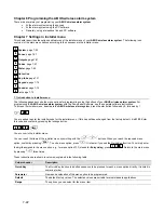
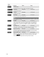
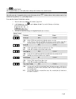
5.5 How do I connect the other contacts in the ABUS wireless alarm system?
5.5.1 Connecting a wired sounder
The
ABUS wireless alarm system
is fitted with a built-in sounder. If required, an external sounder or piezo sounder can be
connected to alert inhabitants and neighbours with a loud signal during the alarm.
To connect an external sounder:
•
Connect the external cables to the sounder clamps (+ Bell) (Bell -). Make sure that the polarity is correct if you are
connecting an electronic sounder and/or polarised sounders.
•
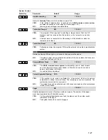
Select the sound signal to be generated (see chapter 8, page 8-29,
Quick Key [1][2][32]
in the installer menu) for
each sounder.
•
For a loudspeaker or built-in sounder driver, the
ABUS wireless alarm system
generates a continuous or
interrupted oscillating voltage.
•
For a sounder or electrical sounder, the
ABUS wireless alarm system
generates a continuous 9V DC or a slow
pulsing voltage, depending on the alarm type. Use a sounder with a maximum power consumption of 9V 500mA.
!
WARNING:
To avoid interference to the external sounder loop if
no
connection is made to the sounder clamps, connect one of
the 2.2 k
Ω
resistors supplied between the (+ Bell) and (Bell -) terminals.
NOTE:
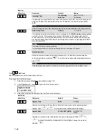
It is very important to define the menu item
Sounder / LS
in the installer menu correctly. The setting depends on
the type of sounder. You normally select the
Sounder
setting.
If the sounder output is overloaded (max. 500 mA) and it is silenced, you have to interrupt the load at the output for
at least 10 seconds before reconnecting a load to the output. The circuit-breaker is then reset.
5.5.2 Sounder tamper
If a sounder tamper contact is fitted, connect the tamper contact of your (wired) sounder with the tamper input on the PC board of
the
ABUS wireless alarm system
(Bell TMP / COM).
This line is protected from tampering by a 2.2 k
Ω
resistor. This should be
connected in series to the contact inside the sounder housing.
The tamper input is monitored only if the setting in the installer menu is set to “Yes” under “External Device” (
Quick Key [1] [2] [31]
in the installer menu
). For more information, see [1] [2] [31].
5.5.3 Controllable relay and transistor outputs
Your
ABUS wireless alarm system
has 4 controllable outputs (2 x 24V DC 3A relays potential-free or 13.8V 200mA and 2 x 13.8V
DC 70mA transistors). These outputs are activated according to system events. For example alarms, system faults, specific zone
and partition events, but also user-controlled or time-controlled.
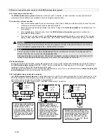
Connect switch outputs
UO1
(switch output 1) and
UO2
(switch output 2) as follows:
AUX
UO2 / UO1
N.O
C
N.C
+
-
J4 (UO2)
or
J5 (UO1)
NEG
EXTERNAL
POW ER
UO2 / UO1
N.O
C
N.C
+
-
J4 (UO2)
or
J5 (UO1)
1 PIN
Only
Positive: Connect the collective
clamp “COM/BLK” and N.C (9V
from NC) with an external
device you want to control via
this switch output. Take note of
jumper J4 (for UO2) and J5 (for
UO1). (See number 15 on page
5-14: What is what inside the
system?)
Negative: Connect the
collective clamp “AUX/RED”
and N.C (9V from AUX) with an
external device you want to
control via this switch output.
Take note of jumper J4 (for
UO2) and J5 (for UO1). (See
number 15 on page 5-14: What
is what inside the system?)
Potential-free: Connect clamps c and
N.C with an external power supply and
an external device you want to control
via this switch output. Take note of
jumper J4 (for UO2) and J5 (for UO1).
(See number 15 on page 5-14: What is
what inside the system?)
+9V
+9V
COM
UO2 / UO1
N.O
C
N.C
+
-
J4 (UO2)
or
J5 (UO1)
POS


