


85
Analog Input PCB
(Optional)
Fitted on Memory
Card Versions only
Remove
tie-bar
Remove PCB
TB2 (if fitted)
TB2
Lift Memory Drive
board (held by
plastic rivets)
Input 1
Input 2
Input 3
Input 4
Input 5
Input 6
Voltage
Current
RTD
THC & mV
Set Link Positions for
optional
inputs
OPTIONAL INPUTS
1
3
5
1
Identify links for
optional
inputs on TB2
4
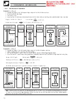
Analog Input PCB
TB1 (Standard )
Fitted on Memory
Card Versions only
Lift Memory Drive board
(held by plastic rivets)
Remove
tie-bar
Remove PCB TB1
Identify link positions
for
Standard
inputs
Set link Positions for S
tandard
inputs
Current
RTD
Voltage
THC & mV
1
2
3
4
5
3
STANDARD INPUTS
Input 1
Input 2
Input 3
Input 4
Input 5
Input 6
7
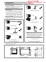
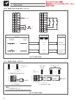
INSTALLATION…
…7.5
Analog Input Connections
(refer to Section 7.9 for 500V isolation option)
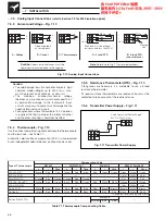
7.5.1
Selecting Standard Analog Inputs – Fig. 7.8
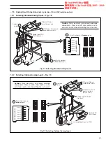
7.5.2
Selecting Optional Analog Inputs – Fig. 7.9
Caution.
Static electricity can seriously damage
components. Wear an earth strap and/or use an
anti-static bench when dismantling the instrument.
Fig. 7.8 Selecting Standard Analog Inputs
Caution.
Static electricity can seriously damage
components. Wear an earth strap and/or use an
anti-static bench when dismantling the instrument.
Fig. 7.9 Selecting Optional Analog Inputs


