68
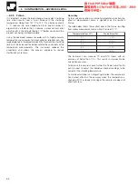
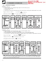
Filter
Level 1 (L1)
Level 2 (L2)
Pump P1
LT
A3 236.7
C
Flowmeter
Manual
Overide
FT
L1 = 2 metres
L2 = 1.8 metres
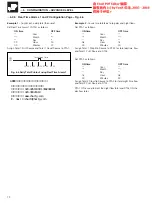
Pump Running Conditions
Pump P1 is to be ON when:
Level falls below L2
and
the time is between 8:00 a.m. and 5:00 p.m.
and
there is no manual overide.
•
•
Input Elements
Alarm A set as a low process alarm with a trip of 1.8m.
Hysteresis for Alarm A set to 0.2m.
Real Time Alarm 1 set ON at 8:00 a.m. and OFF at 5:00 p.m.
Digital Input DA1 set for positive logic so that an:
open contact = normal operation (logic input active)
closed contact = manual overide (logic input non-active).
•
•
Logic Equation – See Below
EQ01 = PAA & RT1 & DA1
…6
CONFIGURATION – ADVANCED LEVEL
Information.
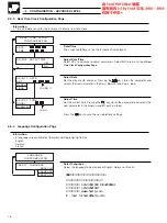
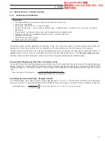
The logic equation can be assigned to a relay to switch the pump on and off. To ensure safe
operation of the system, the output polarity of the relay should be set to POSITIVE, then in the event of a power
failure to the recorder alone, the pump is stopped, leaving the filter in a safe condition.
Fig. 6.4 Pump/Filter Example
6.2.6
Logic Equation Configuration Page – Fig. 6.4
Example
– Liquid in a filter has to be maintained between levels 1 and 2 by switching on and off pump P1. Pump P1 is off during the
night. For filter cleaning, manual override of the pump is required.


