83
A – Instruments with Terminal
Compartment Extension
B – Instruments without Terminal
Compartment Extension
Remove
screws
Remove
backplate
2
1
Power
Supply
Earth
Stud
Analog Inputs
(Standard)
Inputs/Outputs
(Optional)
Power
Supply
Analog Inputs
(Standard)
Earth Stud
Remove
cover
1
Inputs/Outputs
(Optional)
See
Information
below
Undo jacking screw
Pull out chassis
1
2
7
INSTALLATION…
Warning.
Before making any connections, ensure that
the power supply, any high voltage-operated control
circuits and high common mode voltages are switched
off.
7.3
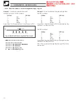
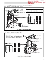
Access to Terminals – Fig. 7.5
7.4
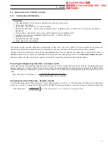
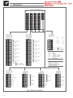
Connections General – Fig. 7.7
The terminals accept cables up to 2.5mm
2
cross section.
For the combination of this apparatus with other apparatus and/
or for its connection to installations, the following notes apply:
Note.
• Always route signal leads and power cables
separately, preferably in earthed metal conduit.
• It is strongly recommended that screened cable is
used for signal inputs and relay connections, with
the screen connected to the earth stud.
7.5
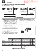
Analog Input Connections
(refer to Section 7.9 for 500V isolation option)
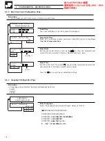
The chassis must be removed to gain access to the analog input
modules when selecting the type of input required.
Open the instrument door and remove the chart unit – see
Fig. 1.7 or 1.8. Remove the chassis as shown in Fig 7.6.
Note.
• For input connections of units with optional 500V
isolation input boards refer to Section 7.9.
• There are no input type selector links for the 500V
option.
Information.
The terminal compartment
extension used for anchoring cable conduits is
an optional fitting.
Fig. 7.5 Access to Terminals
Fig. 7.6 Removing Chassis
广州绿图控仪器仪表有限公司
公司电话: 020-34511909 13042088181
公司传真: 020-39021619
公司网站: www.chartg.com
E - mail :chart@chartg.com
ABB记录纸记录笔打印头供应商:


