background image

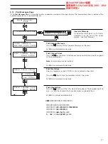
40

                  ON
                 OFF

TEXT PRINT

       NO AUTO PRINT
                  ON
                 OFF

ALARM PRINT

CHART CASSETTE TYPE

          ROLLCHART
            FANFOLD

MESSAGE PRINT SPEED
              FAST
              SLOW

t

n

i

r

P

o

t

r

e

t

e

m

a

r

a

P

d

e

e

p

S

t

r

a

h

C

h

/

m

m

0

2

1

w

o

l

S

d

e

e

p

S

t

n

i

r

P

t

s

a

F

d

e

e

p

S

t

n

i

r

P

s

m

r

a

l

A

s

s

e

c

o

r

P

w

o

l

S

t

s

a

F

s

m

r

a

l

A

e

m

i

T

l

a

e

R

w

o

l

S

t

s

a

F

e

m

i

T

w

o

l

S

w

o

l

S

e

g

n

a

h

C

d

e

e

p

S

t

r

a

h

C

w

o

l

S

w

o

l

S

)

m

m

0

4

2

(

d

e

e

p

S

t

r

a

h

C

e

t

a

D

/

e

m

i

T

w

o

l

S

w

o

l

S

)l

a

n

r

e

t

n

I

e

l

a

c

S

(

s

e

l

a

c

S

w

o

l

S

w

o

l

S

)l

a

n

g

i

S

l

a

t

i

g

i

D

(

s

e

l

a

c

S

w

o

l

S

w

o

l

S

g

a

T

l

e

n

n

a

h

C

r

e

t

c

a

r

a

h

C

0

2

w

o

l

S

w

o

l

S

s

e

u

l

a

V

l

e

n

n

a

h

C

t

s

a

F

t

s

a

F

e

g

a

s

s

e

M

r

o

t

a

r

e

p

O

w

o

l

S

t

s

a

F

k

c

o

l

B

e

g

a

s

s

e

M

r

e

t

c

a

r

a

h

C

0

2

w

o

l

S

t

s

a

F

a

t

a

D

l

e

n

n

a

h

C

t

s

a

F

t

s

a

F

s

r

e

if

i

t

n

e

d

I

e

c

a

r

T

w

o

l

S

w

o

l

S

s

e

u

l

a

V

d

e

z

il

a

t

o

T

t

s

a

F

t

s

a

F

)

t

n

i

r

P

t

s

e

T

(

s

e

l

a

c

S

t

s

a

F

t

s

a

F

…5

CONFIGURATION – BASIC LEVEL

…5.3.1

Chart Control Configuration Page

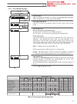
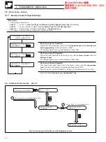
Text Print Enable

Select the text printing required:

NO AUTO PRINT

– disable printing all text that is printed automatically,

i.e. Time, Date, Channel Tags and Trace Identifiers

ON

– enable printing of all text except alarm messages

OFF

– no text printing.

Alarm Print Enable

Select 

ON

 to enable the printing of alarm messages.

Message Print Speed

With chart speeds 

120mm/hr the selections have the following effect:

FAST

– Interrupts chart traces to print alarms or operator message.

SLOW

– Prints alarms or operator message during chart traces.

Above 120mm/hr chart traces are automatically interrupted for fast printing.

Note.

The parameters in the above table are listed in order of the priority in which

they are printed.

Chart Cassette Type

Select the type of chart cassette to be used.

Caution.

Ensure the correct type of cassette is set. Damage to the instrument

may occur if the type is set incorrectly.

Continued on next page.

Summary of Contents for SR100A

Page 1: ...res a parameter value or selection Enter Key Up Down Keys Adjust a parameter value and select a parameter choice Return to Page Header Advancing to Next Page Parameter 1 Parameter 2 Parameter 3 Page 2 Parameter 1 Parameter 2 Parameter 3 Parameter 4 Page 1 Advance to next page Side Scroll Key Moves between pages in menus and between parameters in a page Down Scroll Key Advance to next parameter Mov...

Page 2: ...ce with the information given 4 Normal safety precautions must be taken to avoid the possibility of an accident occurring when operating in conditions of high pressure and or temperature 5 Chemicals must be stored away from heat protected from temperature extremes and powders kept dry Normal safe handling procedures must be used 6 When disposing of chemicals ensure that no two chemicals are mixed ...

Page 3: ...shing Enter Prompt Stores a parameter value or selection Enter Key Up Down Keys Adjust a parameter value and select a parameter choice Return to Page Header Advancing to Next Page Parameter 1 Parameter 2 Parameter 3 Page 2 Parameter 1 Parameter 2 Parameter 3 Parameter 4 Page 1 Advance to next page Side Scroll Key Moves between pages in menus and between parameters in a page Down Scroll Key Advance...

Page 4: ...ns must be taken to avoid the possibility of an accident occurring when operating in conditions of high pressure and or temperature 5 Chemicals must be stored away from heat protected from temperature extremes and powders kept dry Normal safe handling procedures must be used 6 When disposing of chemicals ensure that no two chemicals are mixed Safety advice concerning the use of the equipment descr...

Page 5: ...advanced process recorder can assist pharmaceutical and food processing engineers measure sterilizing temperatures and compute equivalent sterilization times very accurately The simplicity of chart and pen replacement and the clear display of process status make the advanced process recorder easy to operate The recorder is designed for panel mounting and provides complete dust and water protection...

Page 6: ...t No IM SR100AMOD A Standard Documentation Pack B Supplementary Manuals GETTING STARTED Documentation for the advanced process recorder is shown below The Standard Documentation Pack is supplied with all instruments The Supplementary Manuals supplied depend on the specification of the instrument This manual contains information on the Configuration Level programming of the instrument The password ...

Page 7: ...figuration Page Analog Modules 47 5 5 Basic Level Access 48 5 5 1 Security Access Configuration Page 48 5 6 Advanced Level Access 48 Section Page 6 CONFIGURATION ADVANCED LEVEL 49 6 1 Advanced Level Printing 50 6 1 1 Pen Function Configuration Page 50 6 1 2 Message Block Configuration Page Message Blocks 52 6 1 3 Message Block Configuration Page Operator Message 53 6 1 4 Print Channel and Data Val...

Page 8: ...digital signal or from within the Print Messages Page see Section 3 10 Time printed on the nearest hour or half hour after a minimum of 60mm of traces produced Channel Data engineering range and units printed on demand from a digital signal or from within the Print Messages Page Change of Chart Speed and time of change Operator Message printed on demand from a digital signal or from within the Pri...

Page 9: ...HARTS AND PENS 1 2 Instrument Start up Fig 1 2 Caution Ensure that all connections especially to the earth stud are made correctly see Section 7 Switch on the supply to the instrument the input sensors and any power operated control circuits Information When powering the instrument from a DC supply a PSU with a minimum current rating of 5A is recommended Ensure that the voltage supplied is above 1...

Page 10: ...ng Page 2 if selected VIEW DIGITAL SIGNALS PAGE OPERATOR FUNCTION PAGE LOAD CHART PAGE TOTALIZER CONTROL PAGE 1 2 3 4 5 OPERATING PAGE 1 AUTOSCROLL OFF SECURITY ACCESS ENTER CODE 0 No Alarms Present see Information see Information see Information see Information 1 CHARTS AND PENS 1 3 Chart Loading 1 3 1 Selecting the Load Chart Page Figs 1 4 and 1 5 Note Unless otherwise requested all instruments ...

Page 11: ... its previous position and the instrument resumes recording This frame is displayed momentarily if rewind is aborted If all of the chart is rewound before the motor stops press the key When rewind is complete there may still be some chart left to be rewound If this is the case press the key until all remaining chart is rewound Remove the old chart and load the new chart see Fig 1 6 for details Whe...

Page 12: ...ave flap of approx 50mm Tighten chart with thumbwheels 9 10 Lift Catch 1 Remove chart unit 2 1 CHARTS AND PENS 1 3 2 Loading a Roll chart Fig 1 6 Caution Ensure the correct chart type is set in the Chart Control Configuration Page see Section 5 3 1 Fig 1 6 Loading a Roll chart 广州绿图控仪器仪表有限公司 公司电话 020 34511909 13042088181 公司传真 020 39021619 公司网站 www chartg com E mail chart chartg com ABB记录纸记录笔打印头供应商 ...

Page 13: ...n a new chart is fitted and the cassette replaced press the key The chart moves forward approximately 30mm to take up any slack This frame is displayed momentarily when chart loading is complete When the key is pressed recording ceases and the chart stops The print head moves from side to side printing at the 40 and 60 positions on the chart to enable adjustment onto the time line Press the key to...

Page 14: ...les with roller Close guide Fold paper into front tray with square index mark outermost Lift Catch Remove chart unit 1 2 3 4 5 6 7 8 9 10 12 1 1 CHARTS AND PENS 1 3 3 Loading a Fanfold Chart Fig 1 7 Caution Ensure the correct chart type is set in the Chart Control Configuration Page see Section 5 3 1 Fig 1 7 Loading a Fanfold Chart 广州绿图控仪器仪表有限公司 公司电话 020 34511909 13042088181 公司传真 020 39021619 公司网站...

Page 15: ...irmly home on the carrier slides some resistance may be felt as the spring clip locates in the capsule Note After fitting a new capsule the ink flow takes a short time to achieve full color density Two types of pen capsule are available standard and high temperaure The high temperature capsule is designed for use by recorders operating consistently at ambient temperatures above 30 C Fig 1 8 Fittin...

Page 16: ...Basic Level Exit Security Code 1 Incorrect Security Code See Note below SECURITY ACCESS 2 OPERATION BASIC 2 1 Introduction The Operating Level can be configured for either Basic or Advanced operation An overview of the Operator Level pages is contained on the Back Fold out The Basic format is shown in Fig 2 1 and the Advanced in Fig 3 1 Note The Alarm Acknowledge Page is displayed only if an alarm...

Page 17: ...A1 Upper Row Channel number value and units Lower Row bargraph representation of Input A1 Input A2 Input A2 is not displayed on single pen recorders Upper Row Channel number value and units Lower Row bargraph representation of Input A2 Input A3 Input A3 is not displayed on 1 and 2 pen recorders Upper Row Channel number value and units Lower Row bargraph representation of Input A3 Input A4 Input A4...

Page 18: ...0 7 EVENT Pen 1 Pen 2 Pen 3 Trace Event Pen Example 3 Pens Pen Left A4 A5 A6 100 5 200 6 300 7 Pen 4 Pen 5 Pen 6 Pen Right Pen Center 2 OPERATION BASIC 2 2 1 Easy View Facility roll chart only Fig 2 2 The Easy View facility provides an instant view of the latest trace and text to be printed when operating at low chart speeds 120mm and below The chart is wound forward 30mm for approximately 5 secon...

Page 19: ...essage flashes every minute 2hours message flashes alternately with PAPER OUT message Alarms A flashes in the top right hand corner to indicate an alarm condition exists When all active alarms are acknowledged a steady is displayed Note The alarm indicator is displayed only if ON is selected in the Alarm Print Enable frame see Section 5 3 1 This allows alarms to be used for control of external dev...

Page 20: ...ION BASIC 2 3 Alarm Acknowledge Page This page is displayed only when alarms are active and the Acknowledge Type is NORMAL or LATCH see Section 5 2 2 There are three types of alarms Process Alarms Up to 12 alarms assignable to any analog input and activated by pre defined set points see Section 5 2 1 System Alarms Up to 12 input failure alarms activated by an input being outside its pre defined ra...

Page 21: ...essary Security Access can be disabled to allow entry to all pages by setting the code number to 0 see Section 5 5 1 If access to Security Level 3 is not available contact the Customer Support Organization for further information Security Access Enter code number 1 or 3 to obtain access to the Load Chart Page and or the Configuration Level Press the key to enter password Software Version The instr...

Page 22: ...d totals Select reset stop or go Stop recording Cue Review Resume recording Chart Speed Section 3 10 Section 3 9 LOAD CHART PAGE Section 3 7 Section 1 3 If Second Operating Page is not selected If Operator Functions are disabled Basic Level Analog Inputs Advanced Level Serial Comms 9 Configuration Levels see Section 4 If all Totalizers are OFF Allocate operator message Print operator message Print...

Page 23: ...el number value and units Lower Row bargraph representation of Input A1 Input A2 Input A2 is not displayed on single pen recorders Upper Row Channel number value and units Lower Row bargraph representation of Input A2 Input A3 Input A3 is not displayed on 1 and 2 pen recorders Upper Row Channel number value and units Lower Row bargraph representation of Input A3 Input A4 Input A4 is not displayed ...

Page 24: ...o display information in the following formats see Section 6 3 2 3 1 3 Operator Page Messages Power Failure Alternates with top row of frame when the instrument is powered up Press the key to acknowledge This message is displayed only if YES is selected in the Power Failure Indication Enable frame see Section 5 2 2 Paper Low Paper Out Displayed when the remaining chart paper is running low The fre...

Page 25: ...t u b e v i t c a y l s u o i v e r P e v i t c a n I 3 OPERATION ADVANCED Process Alarms Up to 12 alarms assignable to any analog input and activated by pre defined set points see Section 5 2 1 System Alarms Up to 12 input failure alarms activated by an input being outside its pre defined range Real Time Event Up to 2 alarms activated at a pre defined time see Section 6 2 8 Note is displayed inst...

Page 26: ... page and the View Digital Signals Page are included only if YES is selected in the Signal Page Enable frame see Section 6 3 1 View Analog Signals Page All assigned analog inputs and math blocks can be viewed including any input not displayed in Operating Pages 1 and 2 Analog Input Math Block Use the and keys to select the analog input or math block to be viewed 3 4 View Digital Signals Page This ...

Page 27: ... are set to NONE totalizer OFF in the Totalizer Configuration Page see Section 6 4 2 Notes 1 Each totalizer defaults to GO when set up in the Totalizer Configuration Page see Section 6 4 2 2 Counter Stop Go Press the key from the Counter Reset loop to enter the Counter Stop Go loop The page remains in this loop until the Counter Reset loop is re selected or the page is exited Select GO to start th...

Page 28: ...it Review Cue and advance to Set Chart Speed If fast printing of text is in progress the chart does not stop until printing is complete Press to store the selection Once recording is stopped data is not buffered and therefore incoming data cannot be printed on the chart Review Cue Use review and cue to rewind or advance the roll chart to examine a specific occurrence Pressing the key causes record...

Page 29: ...ecurity Code 1 No Security Code If Signal Page Enable is set to NO Security Code 3 SECURITY ACCESS 3 OPERATION ADVANCED 3 7 Security Access A security system prevents tampering with the secure parameters by utilizing three levels of access Security Level 1 access to Load Chart Page Security Level 2 access to Process Review Page and Print Messages Page Security Level 3 access to the Configuration L...

Page 30: ... either YES to advance or NO to return to top of page Press the key to store the selection Once recording is stopped incoming data is not buffered and therefore cannot be printed on the chart Move To Alarm Occurrence The chart can be automatically rewound to any one of the above alarm buffers On entering the desired buffer identity number the lower chart display changes to SEARCHING and the chart ...

Page 31: ...the key to print the Operator Message on the chart ACKNLG is displayed momentarily Print Channel Values Press the key to print an instantaneous value and units of any inputs assigned to the recording pens Note Event markers are not printed ACKNLG is displayed momentarily Print Total Values Select a single total or ALL TOTALS to be printed on the chart Press the key to store the selection and print...

Page 32: ...e grouped into sub levels within the major levels 4 1 Controls Fig 4 1 Movement between pages and parameters uses the same controls as the operating pages see Front Fold out The controls used to move between levels and from the page tops back to the configuration levels are shown in Fig 4 1 Tags and messages can be entered at set parameters within the configuration pages The illustration on the Fr...

Page 33: ...Input to adjust Reset scale adjust Adjust offset Adjust span Select alarm to configure Set up alarm Set acknowledge type Power failure indication Configure chart speeds and sources Text Alarms print on off Cassette type Fast Slow print Easy View Time line advance Pen lift Auto rewind Select scale to configure Configure scale Enable pen calibration Select chart zero or full scale Configure module i...

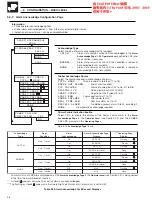
Page 34: ... to 20 mA displaying a range of 0 to 200psi a fault detection level 10 above 200psi engineering display range and 10 below 0psi engineering display range in the event of a fault being detected and or the fault detection level being exceeded the process variable is driven downscale 5 1 Basic Level Analog Inputs 5 1 1 Analog Input Configuration Page Information Up to 12 analog inputs on standard boa...

Page 35: ...e OFF Sets input to off analog I P A1 cannot be turned off For thermocouple applications using an external fixed cold junction select mV input type Note Before selecting input types other than TC and mV ensure links are set correctly see Section 7 5 1 Linearizer Type Select the linearizer type required 5 2 x5 2 3 2 x3 2 SQRT Square root CUSTOM As set in Math Functions Configuration Level RTD Resis...

Page 36: ...ken Sensor Drive Select the broken sensor drive required UP Upscale drive DOWN Downscale drive NONE No drive Fault Detection A fault level percentage can be set to detect a deviation above or below the input span Set the value required between 0 0 and 100 0 of the display range in 0 1 increments Example for a 10 setting on an input range of 100 to 200mV a fault is detected at 90mV and 210mV Filter...

Page 37: ... 1 1 5 4 5 CONFIGURATION BASIC LEVEL 5 1 2 Input Conditioning Configuration Page Information Mains filter selectable for maximum noise rejection Quick input configuration feature copies channel A1 settings to all other inputs for applications where all the inputs are the same Rejection Frequency Select the mains rejection frequency required 50Hz or 60Hz Copy A1 Input Configuration Allows the confi...

Page 38: ...ved using Offset Adjustment System Scale Errors can be removed using Span Adjustment Offset span Adjustment can be used to perform spot calibration Switch off the power supply to the instrument Connect accurate signal sources suitable for simulation over the entire input range in place of each analog input connection A1 to A6 terminals TB1 1 to 18 and B1 to B6 terminals TB2 1 to 18 if fitted For t...

Page 39: ...B1 to B6 depending on the options fitted see Section 4 2 On entry the default is NONE Scale Adjustment Reset Select YES to reset the analog input offset and span values to their nominal values Offset Adjustment Electrical and resistance thermometer inputs apply the correct input for the spot calibration required For RTD inputs use resistance values obtained from standard tables Thermocouple inputs...

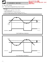
Page 40: ...2 1 Process Alarm Configuration Page Figs 5 2 and 5 3 Information 12 Process alarms identified A to M excluding I High low process alarms Alarms assignable to any analog input or math result Adjustable hysteresis value to prevent oscillation of alarm state Alarms can trigger printing of messages see Sections 6 1 2 and 6 1 3 Fig 5 2 High Process with Hysterisis Fig 5 3 Low Process with Hysterisis ...

Page 41: ...OCESS Alarm activated when process rises above trip level Alarm Source An alarm source is assigned to the alarm identity selected above Select the alarm source required from analog inputs A1 to A6 B1 to B6 depending on the options fitted see Section 4 2 and math functions M1 to M4 Trip Level Set the trip level for the alarm selected above the trip level set should not exceed the display range limi...

Page 42: ...f the Power Failure alarm in the Alarm Acknowledge Page in the Operator Level see Section 2 3 and the POWER FAILED message in the Operating Pages Return to Acknowledge Type frame An alarm status of CLEAR is displayed only if the Alarm Acknowledge Page in the Operator Level see Section 2 3 is being viewed at the time the alarm becomes inactive A steady appears only when ALL active alarms are acknow...

Page 43: ...Select a chart speed between 0 and 1500mm hr Chart Speed 1 Source Select the source required to initiate a change to chart speed 1 TOTAL WRAP Wrap around of a totalizer T1 to T6 PAPER OUT ALARM End of chart reached I P FAILURE Failure of analog input A1 to A6 B1 to B6 DIGITAL I P Active digital input DA1 to DG3 CHART SPEED Selection of chart speed 1 to 3 LOGIC EQN Logic equation true 1 to 10 POWER...

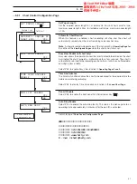
Page 44: ... e u l a V d e z i l a t o T t s a F t s a F t n i r P t s e T s e l a c S t s a F t s a F 5 CONFIGURATION BASIC LEVEL 5 3 1 Chart Control Configuration Page Text Print Enable Select the text printing required NO AUTO PRINT disable printing all text that is printed automatically i e Time Date Channel Tags and Trace Identifiers ON enable printing of all text except alarm messages OFF no text printi...

Page 45: ... View Enable roll chart only Easy view allows the operator to view the latest printed information on the chart by winding the chart forward a small distance for a few seconds The chart is automatically returned to the recording position where it prints any buffered data ensuring no loss of data Select YES to enable Easy View function in Operating Pages 1 and 2 Time Line Advance The time line funct...

Page 46: ... not the actual chart length If automatic scale printing is not required select OFF Scale Pen Select the pen color to be used to print the selected scale refer to Table 5 5 on page 43 for pen options Set Full Scale Select the full scale value for the scale between 999 and 9999 Set Decimal Point Select the number of decimal places for the scale 0 1 or 2 Set Zero Select the zero value for the scale ...

Page 47: ...ion of the pen positions on the chart Can be used to remove effects of inconsistencies in the charts Pen Calibration Enable Select YES to advance to the zero and full scale setting parameters Chart Zero Position The chart advances at high speed and the pen moves to its zero position With the door open set the chart zero position of pen 1 Magenta Red using the and keys Press the key to store the pe...

Page 48: ...utput T1 to T6 TOTAL WRAP Wrap around of a totalizer T1 to T6 PAPER OUT ALARM End of chart reached I P FAILURE Failure of analog input A1 to A6 B1 to B6 DIGITAL I P Active digital input DA1 to DG3 CHART SPEED Selection of chart speed 1 to 3 LOGIC EQN Logic equation true 1 to 10 POWER FAILURE After power failure REAL TIME ALM Real time alarm on 1 or 2 PROCESS ALARM Pre defined process alarm A to M ...

Page 49: ...uts are allocated according to the module location of the board i e DB1 3 to DG1 3 Circuit 1 Digital Output Source Select the source required to activate the digital output TOTAL COUNT Totalizer pulse output T1 to T6 TOTAL WRAP Wrap around of a totalizer T1 to T6 PAPER OUT ALARM End of chart reached I P FAILURE Failure of analog input A1 to A6 B1 to B6 DIGITAL I P Active digital input DA1 to DG3 C...

Page 50: ...Output module contains three relay output circuits Circuit 1 Relay Output Source Select the source required to activate the relay output TOTAL COUNT Totalizer pulse output T1 to T6 TOTAL WRAP Wrap around of a totalizer T1 to T6 PAPER OUT ALARM End of chart reached I P FAILURE Failure of analog input A1 to A6 B1 to B6 DIGITAL I P Active digital input DA1 to DG3 CHART SPEED Selection of chart speed ...

Page 51: ...ll scale value of the output source selected above Circuit 1 Zero Current Set the output current required to represent the zero value of the output source selected above Circuit 2 Analog Output Source Select the source required to activate the analog output as for circuit 1 above Circuit 2 Full Scale Current Set the output current required to represent the full scale value of the output source sel...

Page 52: ...evel 1 and 2 pages Configuration Level This page is used to set the passwords for the security levels Set Access Level 1 Password The Level 1 password allows access to the Load Chart Page and the Memory Card Data Logging Setup if a Memory card is fitted Set the password to any number between 0 and 1999 Set Access Level 2 Password The Level 2 password allows access to Level 1 and the Process Review...

Page 53: ... user defined linearizer input Set alarm on off date and time Allocate alarm message Set alarm on off date and time Allocate alarm message Sections 6 2 1 to 6 2 5 Section 6 2 6 Section 6 2 7 Section 6 2 8 Section 6 2 8 PEN FUNCTION CONFIGURATION MESSAGE BLOCK CONFIGURATION CHANNEL VALUES PRINT TOTAL VALUES PRINT CONFIGURATION CONFIGURATION Select pen to configure Configure pen Set up 14 message bl...

Page 54: ...n 1 cannot be set to NONE Pen Trend Source Select the input required for a standard trace The input sources are selected from analog inputs A1 to A6 B1 to B6 depending on the options fitted see Section 4 2 or math functions M1 to M4 Return to Pen to Configure parameter Pen Event Source LEFT Select the event source required TOTAL WRAP Wrap around of a totalizer T1 to T6 PAPER OUT ALARM End of chart...

Page 55: ...RIGHT Select the event source as for LEFT previous page With an event occurrence the pen moves approximately 3mm to the right of the central position within the zone set below Pen Event Zone Select the event zone required Zones 1 to 6 are positioned equidistant across the chart from zero to full scale see Fig 6 2 Return to Pen to Configure frame Fig 6 2 Chart Event Zones 广州绿图控仪器仪表有限公司 公司电话 020 345...

Page 56: ...n Block Message Set the required message required on the upper display see Front Fold out Block Source Select the required source to activate the printing of the message block TOTAL WRAP Wrap around of a totalizer T1 to T6 PAPER OUT ALARM End of chart reached I P FAILURE Failure of analog input A1 to A6 B1 to B6 DIGITAL I P Active digital input DA1 to DG3 CHART SPEED Selection of chart speed 1 to ...

Page 57: ...Operator Message Set the required message required on the upper display see Front Fold out Message Source Select the required source to activate the printing of the operator message TOTAL WRAP Wrap around of a totalizer T1 to T6 PAPER OUT ALARM End of chart reached I P FAILURE Failure of analog input A1 to A6 B1 to B6 DIGITAL I P Active digital input DA1 to DG3 CHART SPEED Selection of chart speed...

Page 58: ...p Page Information Printing of up to 12 channel values Channel identity value and engineering units printed for each channel Printing can be triggered from internal or external digital signal or at pre configured time intervals Note Channel values are always fast printed Value Print Source and Pen Select an input source for each of the 12 channel values to be printed The input sources are selected...

Page 59: ...T s r u o H 8 y r e v E d n a t h g i n d i M s r u o H 2 1 y a d d i M d n a t h g i n d i M s r u o H 4 2 t h g i n d i M 6 CONFIGURATION ADVANCED LEVEL 6 1 4 Print Channel and Data Values Setup Page Automatic Print Time Select the time interval required between each set of printed values The time interval is selectable in 5 10 15 20 30 min and 1 2 4 6 8 12 24 hr intervals Automatic printing can...

Page 60: ...ls Note Totalizer values are always fast printed Totalizer Print Source and Pen Select the source required to initiate printing of each of the six totalizers The totalizers can be printed in any of the available colors Refer to Table 5 5 on page 43 for pen options TOTAL WRAP Wrap around of a totalizer T1 to T6 PAPER OUT ALARM End of chart reached I P FAILURE Failure of analog input A1 to A6 B1 to ...

Page 61: ... v E d n a t h g i n d i M s r u o H 3 r e t f a e r e h T s r u o H 3 y r e v E d n a t h g i n d i M s r u o H 4 r e t f a e r e h T s r u o H 4 y r e v E d n a t h g i n d i M s r u o H 6 r e t f a e r e h T s r u o H 6 y r e v E d n a t h g i n d i M s r u o H 8 r e t f a e r e h T s r u o H 8 y r e v E d n a t h g i n d i M s r u o H 2 1 y a d d i M d n a t h g i n d i M s r u o H 4 2 t h g i...

Page 62: ...et Block to Configure Select the math block to configure M1 to M4 On entry the default is NONE Math Function Select the math function required FVALUE Fvalue calculation RH Relative Humidity calculation MASS FLOW 2 Calculation of mass flow from differential pressure MASS FLOW 1 Calculation of mass flow from volume flow axb c Equivalent to straight line equation y mx c a b c a b c Simple arithmetic ...

Page 63: ...ch represents the minimum result value between 999 and 9999 Engineering Units Engineering units of up to six characters can be set on the upper display see Front Fold out Math Result Tag A result description of up to twenty characters can be set on the upper display see Front Fold out See Section 6 2 2 See Section 6 2 3 See Section 6 2 4 See Section 6 2 5 广州绿图控仪器仪表有限公司 公司电话 020 34511909 1304208818...

Page 64: ...r input a The source is selected from analog inputs A1 to A6 B1 to B6 depending on the options fitted see Section 4 2 or math functions M1 to M4 Input Constant Value Set an arithmetic value between the values 999 and 9999 Input Constant Decimal Point Set the number of decimal places for the input 0 to 3 places Input b Select the type source or constant as required for input b The method is as for ...

Page 65: ... from analog inputs A1 to A6 B1 to B6 depending on the options fitted see Section 4 2 or math functions M1 to M4 Return to Block to Configure frame 6 2 3 Relative Humidity RH The relative humidity calculation requires two inputs one from a wet bulb sensor and one from a dry bulb sensor Both of these inputs are configured as variables RH tables are based on the use of an aspirated pyrochrometer hav...

Page 66: ...no additional linearization within the advanced process recorder is required Where the input from the differential pressure sensor is linear to differential pressure head the square root linearizer within the advanced process recorder s Analogue Input Configuration Page must be used The formula used internally is ii M k a P Tr T Pr where input a linearized flow signal The linearized flow signal is...

Page 67: ... has a mass of 8 334 lbs To calculate the mass flow of water from the volume flow the following settings are used A1 volume flow of water gal min A2 temperature of water F A3 absolute pressure of water psia M2 result of math block 2 lb min Mass Flow 1 k V P Tr Pr T therefore the equation is M lb min 8 334 x Volume gal min x measured absolute pressure PSIA x 520 R 14 696 psia measured temperature R...

Page 68: ...ured in C ABSOLUTE K or R Input source measured in degrees absolute Reference Temperature Set the value which represents the reference temperature between 0 and 9999 The decimal point is set in the next parameter Reference Temperature Decimal Point Set the number of decimal places required for the reference temperature 0 to 3 places Pressure Input Source Select the input source required for the ab...

Page 69: ...ocesses the actual sterilizing temperature varies depending on the products involved and on each sterilization process Calculation Fig 6 3 The advanced process recorder s advanced Fvalue implementation takes the Fvalue into account and allows the process engineer to compute both steam Fo and dry heat Fh results with user defined target sterilization temperatures and Z values The function implement...

Page 70: ...t be increased to compensate for the uncertainty of the temperature measurements The instrument reduces this uncertainty and allows the process engineer to reduce sterilization cycle times Accuracy As the Fvalue calculation is essentially a logarithmic function the effect of measurement errors is significant on the resultant Fvalue The table below shows the resultant error in the Fvalue resulting ...

Page 71: ...ber of decimal places for the Z Factor 0 to 3 places Start Source Select the digital source to start or reset the Fvalue calculation Example Set the high process alarm to start the Fvalue calculation when the measured temperature reaches 100 C End Source Select the digital source to end the Fvalue calculation Example Set the high process alarm to end the Fvalue calculation when the math result rea...

Page 72: ...ut active closed contact manual overide logic input non active Logic Equation See Below EQ01 PAA RT1 DA1 6 CONFIGURATION ADVANCED LEVEL Information The logic equation can be assigned to a relay to switch the pump on and off To ensure safe operation of the system the output polarity of the relay should be set to POSITIVE then in the event of a power failure to the recorder alone the pump is stopped...

Page 73: ... used as an activation event Terminator used to complete the expression Close bracket Open Bracket Logical AND Logical OR T1W T6W Wrap around of totalizer T1 to T6 P_O Paper Out alarm FA1 FB6 Input failure A1 to A6 B1 to B6 DA1 DG3 Digital input active CS1 CS3 Chart speeds L1 L10 Logic equation true PWR Power failure RT1 RT2 Real time alarm on 1 or 2 PAA PAM Predefined process alarm A to M excludi...

Page 74: ...X4 X5 Y2 Y3 Y4 Y5 6 CONFIGURATION ADVANCED LEVEL 6 2 7 Custom Linearizer Configuration Page Fig 6 5 Information Single 20 point custom linearizer Variable spacing on x and y axis to allow optimization of breakpoints Set custom linearizer X and Y breakpoints Up to twenty X and Y points are set to create the linearizer function required Set each value between 0 0 and 100 0 Note The process variable ...

Page 75: ... a daily basis set Note The settings have to be entered sequentially starting with every year and working down to every hour If a specific date is set and subsequently the on time is e g set to 15 the date would automatically be changed to Alarm On Time Set the alarm on time Pressing the key advances the selection between Hours and Minutes Hours can be set to allowing the alarm to be activated at ...

Page 76: ... 06 Hour 18 00 Minutes 00 Assign Total 1 Stop Go Source to RTA1 for total daytime flow and Total 1 Print Source to RTA2 Set RTA2 as follows ON time OFF time Year Month Day 18 Hour 06 00 Minutes 00 Assign Total 2 Stop Go Source to RTA2 for total night time flow and Total 2 Print Source to RTA1 RTA1 ON is used to print the night flow total and RTA2 ON the day flow total Fig 6 6 Daily Total Printout ...

Page 77: ...erating level complexity If BASIC is selected the following pages are not included in the Operating Level Operating Page 2 View Analog Signals Page View Digital Signals Page Totalizer Control Page Operator Function Page Print Messages Page Processes Review Page Memory Card Data Logging Set up Signal Page Enable Select YES to enable the View Analog Signals Page and the View Digital Signals Page in ...

Page 78: ... Example 6 Pens A1 A2 100 3 400 7 EVENT Pen 1 Pen 2 Pen 3 Trace Event Pen Example 3 Pens Pen Left A4 A5 A6 100 5 200 6 300 7 Pen 4 Pen 5 Pen 6 Pen Right Pen Center 6 CONFIGURATION ADVANCED LEVEL 6 3 2 Operating Pages 1 and 2 Configuration Page Fig 6 7 Information 2 Operating Pages 8 programmable frames for each page 4 frame types Standard Totalizer Digital Signal or Pen Values Programmable Operati...

Page 79: ...able see Fig 6 6 page 72 PEN VALUE Displays the inputs assigned to the pens Up to 3 inputs can be displayed in one frame DIGITAL Any one of up to 47 sources from digital inputs alarms logic equations or chart speeds TOTALISER Any one of six totalizers STANDARD Any one of up to 12 analog inputs see Section 4 2 or four math functions OFF All but frame 1 of Operating Page 1 can be set to OFF Frame So...

Page 80: ...turn to top of Real Time Clock Configuration Page Adjust Date Set the day month and year Pressing the key stores the parameter and selects the next parameter in the Day Month and Year loop Adjust Time Set the current time Pressing the key stores the parameter and selects the next parameter in the Hours and Minutes loop Press the key to save the new date time settings 6 3 4 Language Configuration P...

Page 81: ...l An additional internal Secure total is also provided which can be reset only after gaining access to the Advanced Configuration Level External counters with their own power supplies can be driven using relay and digital output module options Converting the Engineering Flow Rate Example A and B To calculate the count rate high the engineering flow rate high must first be converted into units per ...

Page 82: ...hour measuring effluent discharge count every 0 01m3 wrap function ON front panel total automatically reset to 0 and continues counting when predetermined value is reached Range 150 000 l h 150m3 h Totalizer count full scale 4 17 pulses s OK maximum is 10 0 0417 0 01 Units second 0 0417m3 s 150 3 600 Note For the majority of applications the Count Rate Low is set to 0000 Only if the engineering Fl...

Page 83: ...re Total The secure total for the totalizer selected above is displayed This value is independent of the displayed flow total and can comprise up to ten digits as set in the Totalizer Decimal Point parameter see below Select YES and press enter to reset the secure total The figure displayed depends on the type of counter selected UP or DOWN Totalizer Count Full Scale Set the required count pulses ...

Page 84: ...er Front Panel Reset Enable When front panel reset is enabled the flow total can be reset to the preset value from the Totalizer Page see Section 3 5 Select YES to enable the reset Totalizer Reset Source Select the source required to automatically activate the totalizer reset TOTAL WRAP Wrap around of a totalizer T1 to T6 PAPER OUT ALARM End of chart reached I P FAILURE Failure of analog input A1 ...

Page 85: ...cations where walkie talkies are expected to be used screened cables within earthed metal conduit must be used Fig 7 2 Environmental Requirements Fig 7 3 Overall Dimensions EC Directive 89 336 EEC In order to meet the requirements of the EC Directive 89 336 EEC for EMC regulations this product must not be used in a non industrial environment End of Life Disposal This instrument does not contain an...

Page 86: ...y tightening the panel clamp retaining screws see Caution below 30 max Cut a hole in the panel see Fig 7 3 for dimensions Remove the panel clamps 1 2 3 4 5 6 7 3 7 INSTALLATION 7 2 Mounting Figs 7 3 and 7 4 Caution The clamp must fit flat against the instrument case If the clamp is bowed the securing screw is too tight and sealing problems may occur Fig 7 4 Mounting 广州绿图控仪器仪表有限公司 公司电话 020 34511909...

Page 87: ...apply Note Always route signal leads and power cables separately preferably in earthed metal conduit It is strongly recommended that screened cable is used for signal inputs and relay connections with the screen connected to the earth stud 7 5 Analog Input Connections refer to Section 7 9 for 500V isolation option The chassis must be removed to gain access to the analog input modules when selectin...

Page 88: ... ve ve Earth 2 wire Transmitter DC Power Power Supply Section 7 8 C1 C2 C3 C4 C5 C6 C7 C8 C9 C10 B1 B2 B3 B4 B5 B6 B7 B8 B9 B10 Analog I P B1 Analog I P B2 Analog I P B3 Analog I P B4 Analog I P B5 Analog I P B6 3rd lead RTD 3rd lead RTD 3rd lead RTD 3rd lead RTD 3rd lead RTD 3rd lead RTD Instrument viewed from rear AUX PWR TB1 TB2 TB3 TB4 A 1 A 2 A 3 A 4 A 5 A 6 A 7 A 8 A 9 A 10 A 11 A 12 A 13 A ...

Page 89: ...Standard inputs Set link Positions for Standard inputs Current RTD Voltage THC mV 1 2 3 4 5 3 STANDARD INPUTS Input 1 Input 2 Input 3 Input 4 Input 5 Input 6 7 INSTALLATION 7 5 Analog Input Connections refer to Section 7 9 for 500V isolation option 7 5 1 Selecting Standard Analog Inputs Fig 7 8 7 5 2 Selecting Optional Analog Inputs Fig 7 9 Caution Static electricity can seriously damage component...

Page 90: ... I D n o C e F 0 1 7 3 4 N I D d e r e u l B e u l B e u l B 7 INSTALLATION 7 5 Analog Input Connections refer to Section 7 9 for 500V isolation option 7 5 3 Current and Voltage Fig 7 10 Caution To avoid damage to multi channel instruments high common mode voltages up to 250V r m s max must be present on all channels or not at all The maximum channel to channel voltage between any two channels mus...

Page 91: ...witching either positive or negative logic can be selected using the plug in links LK5 The digital input DA1 terminals A19 and A20 see Fig 7 7 has fixed positive logic 7 6 2 Selecting the Digital Output Configuration Fig 7 15 Each digital output can be selected to either TTL or open collector using the plug in links 2 3 or 4 If an open collector type output is selected then a further selection can...

Page 92: ...3 B TTL Output Link 2 3 or 4 see Fig 7 13 Open Collector Output TTL Output or A Digital O P Type Selector Link 24V 5V 0V O P 1 2 3 O P 1 4 O P 2 5 O P 3 6 24V 5V 0V O P C Open Collector Output Link 1 see Fig 7 13 With diode protection Without diode protection no link or or 1 2 3 O P 1 4 O P 2 5 O P 3 6 See Note 1 See Note 2 See Note 2 See Note 2 5V 24V 7 INSTALLATION 7 6 3 Digital Input Connection...

Page 93: ... measurements Maximum millivolt range 2000mV All standard current and thermocouple ranges apply Notes Applicable to CSA certified units only If 4 relay output modules are fitted then no additional option modules are allowed and module positions F and G see Fig 7 7 must remain vacant The maximum total combined current flowing through the relays is 36A the individual relay current of 5A remains unal...

Page 94: ... r o c n i o t e u d d n e f f o e m o c s a h r e p a P d e r e t n e g n i e b h t g n e l d n i w e r e s u d n a r e l l o r d e e f o t n o r e p a p d a o l e R l l o r w e n r o f d e r e t n e s i h t g n e l r e p a p t c e r r o c e r u s n E 1 3 5 n o i t c e S e e s n o n o i t i s o p t c e r r o c o t n r u t e r t o n s e o D w e i v e R e u C r e t f a t r a h c e t t e s s a c h t...

Page 95: ...9005F Pen capsule Up to three traces PR100 0210 Up to three traces high temperature see Note below PR100 0229 Four to six traces PR100 0211 Four to six traces high temperature see Note below PR100 0230 Memory card 64kbyte B10798 1Mbyte B10865 Note The high temperature cartridge is designed for use by recorders operating at ambient temperatures consistently above 30 C 9 2 Replacement Parts Item Par...

Page 96: ...ll 5 13 19 B Bargraph 13 19 75 Broken Sensor Drive 32 C Capacitors 91 Chart Control Configuration 39 Length 13 19 Loading Fan Fold Chart 9 Roll Chart 7 Paper Low Alarm 15 Printout 4 Rewind 6 Scales 42 Set Length 41 Set Speed 24 Speed 6 8 24 39 Clock Real Time 76 Configuration Analog Inputs 30 Chart Control 39 Scaling 42 Digital Output 87 Input Conditioning 33 Language 76 Logic Equation 68 Maths Bl...

Page 97: ...3 Operating Page 2 19 Operator Message 26 Print Speed 40 Output Module Analog Modules 47 Digital Modules 45 Hybrid Modules 44 Relay Modules 46 Output Polarity 45 P Paper Length 41 Password 3 25 48 Pen Auto Drop Enable 41 Capsule Fitting 11 Event Source 50 51 Function Configuration 50 Lift Enable 41 Options 43 Position Configuration 43 Select Values 75 Power Failure 15 Power Supply Connections 89 P...

Page 98: ... Setting 13 19 76 Time Line Advance 41 Totalization Configuration 79 Introduction 77 Source 79 Totalizers 23 Front Panel Stop Go Enable 80 Predetermined Value 80 Preset Value 80 Wrap around Enable 80 Transmitter Power Supply 86 V Viewing Analog Signals 22 Digital Signals 22 Z Z Factor 67 广州绿图控仪器仪表有限公司 公司电话 020 34511909 13042088181 公司传真 020 39021619 公司网站 www chartg com E mail chart chartg com ABB记录...

Page 99: ...Drives and Motors AC and DC Drives AC and DC Machines AC Motors to 1kV Drive Systems Force Measurement Servo Drives Controllers Recorders Single and Multi loop Controllers Circular Chart and Strip Chart Recorders Paperless Recorders Process Indicators Flexible Automation Industrial Robots and Robot Systems Flow Measurement Electromagnetic Flowmeters Mass Flow Meters Turbine Flowmeters Flow Element...

Page 100: ...ation Operating Level Contents Operating Page s Configuration Real Time Clock Configuration Language Configuration Totalizer Configuration Advanced Configuration Levels Access Advanced Level Disabled Section 5 2 Section 5 3 Section 5 4 Section 5 5 Section 5 6 Section 6 1 Section 6 2 Section 6 3 Section 6 4 Process Alarm Configuration Alarm Acknowledge Page Enter Key Pen Function Configuration Mess...

Page 101: ...lers Circular Chart and Strip Chart Recorders Paperless Recorders Process Indicators Flexible Automation Industrial Robots and Robot Systems Flow Measurement Electromagnetic Flowmeters Mass Flow Meters Turbine Flowmeters Flow Elements Marine Systems Turbochargers Electrical Systems Marine Equipment Offshore Retrofit and Refurbishment Process Analytics Process Gas Analysis Systems Integration Trans...

Page 102: ... Real Time Clock Configuration Language Configuration Totalizer Configuration Advanced Configuration Levels Access Advanced Level Disabled Section 5 2 Section 5 3 Section 5 4 Section 5 5 Section 5 6 Section 6 1 Section 6 2 Section 6 3 Section 6 4 Process Alarm Configuration Alarm Acknowledge Page Enter Key Pen Function Configuration Message Block Configuration Channel Values Print Configuration To...

Reviews: