Assembly Instructions
Assembly
1HSB435410-2 enrev1
19
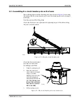
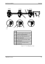
4.9.2 Assembling the pull-rods between operating mechanism and pole A1.
Each pole is supplied set to a basic setting and its Close and Open positions are
determined. Adjustment is made as set out below (see
Figure 4-14
).
•
Move by hand the operating lever (3) and the pull-rod from the operating
mechanism (2) towards its Close position sufficiently far so that the pull-rod
(5) can be placed between the coupling link (4) and the pull-rod from the
operating mechanism.
•
Simultaneously screw the pull-rod (5) into the operating mechanism’s pull-rod (2)
(right-hand thread) and the pole’s coupling link (4) (left-hand thread).
N.B.
Remember the two spring washers (6) under each locking nut (8).
•
Turn the pull-rod (5) so its length decreases at the same time as the operating
lever (3) moves towards its Open position. The pull-rod (5) is the right length
when the operating lever (3) is in its Open position and the alignment
check hole (7) is directly aligned with the predrilled hole in the mechanism
housing (1). Check the position of the hole using a rod with a 6 mm diameter.
Check that the pull-rod (5) is screwed past the alignment check holes (9 and
10). The tightening torque for the locking nuts is 300 Nm.
Figure 4-14. Assembling the pull-rod between the operating mechanism and pole A1.
Item
1
Mechanism housing
2
Pull-rod from operating
mechanism
3
Operating lever
4
Coupling link, pole
5
Pull-rod (turnbuckle
screw)
6
Spring washers
7
Alignment check hole
in arm
8
Locking nuts
9
Alignment check hole
in pull-rod
10
Alignment check hole
in coupling link
1
2
3
4
5
6
9
8
10
7
B10133
TIGHTENING TORQUE
300 Nm
Summary of Contents for SF6 LTB 245E1 BLG 1002A
Page 1: ...Product Manual 1HSB435416 2 en Rev 1 LTB 245E1 BLG 1002A 3 pole operation ...
Page 92: ...ABB Switchgear SF6 Circuit Breaker Circuit breakers HPL and LTB 1HSB445409 1 en0 Lubricants ...
Page 198: ......
Page 199: ......
Page 209: ......
Page 210: ......


