L2234
Emax
150/158
Doc. No.
Model
1SDH000460R0002
Apparatus
Scale
Page No.
L2778
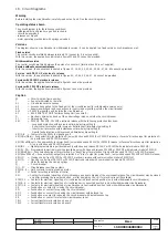
TI/L3
= Current transformer located on phase L3
TO
= Homopolar toroidal current transformer (see note W)
Vaux
= Auxiliary power supply voltage (see note F)
UI/L1
= Current sensor (Rogowski coil) located on phase L1
UI/L2
= Current sensor (Rogowski coil) located on phase L2
UI/L3
= Current sensor (Rogowski coil) located on phase L3
UI/N
= Current sensor (Rogowski coil) located on neutral
UI/0
= Current sensor (Rogowski coil) located on the conductor connecting to earth the star point of the MV/LV transformer (see note G)
W1
= Serial interface with control system (external bus): EIA RS485 interface (see note E)
W2
= Serial interface with the accessories of PR121/P, PR122/P and PR123/P releases (internal bus)
X
= Delivery connector for auxiliary circuits of withdrawable version circuit-breaker
X1...X7
= Connectors for the accessories of the circuit-breaker
XF
= Delivery terminal box for the position contacts of the withdrawable circuit-breaker (located on the fixed part of the circuit-breaker)
XK1
= Connector for power circuits of PR121/P, PR122/P and PR123/P releases
XK2 - XK3 = Connectors for auxiliary circuits of PR121/P, PR122/P and PR123/P releases
XK4
= Connector to signal open/close
XK5
= PR120V module connector
XO
= Connector for YO1 release
XV
= Delivery terminal box for the auxiliary circuits of the fixed circuit-breaker
YC
= Shunt closing release
YO
= Shunt opening release
YO1
= Overcurrent shunt opening release (trip coil)
YO2
= Second shunt opening release (see note Q)
YR
= Coil to electrically reset the circuit-breaker
YU
= Undervoltage release (see notes B and Q)
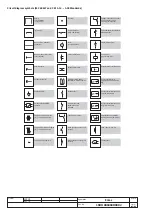
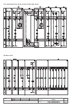
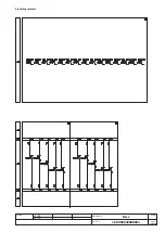
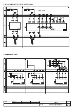
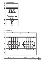
Description of figures
Fig. 1
= Motor circuit to load the closing springs.
Fig. 2
= Circuit of shunt closing release.
Fig. 4
= Shunt opening release.
Fig. 6
= Instantaneous undervoltage release (see notes B and Q).
Fig. 7
= Undervoltage release with electronic time-delay device, outside the circuit-breaker (see notes B and Q)
Fig. 8
= Second shunt opening release (see note Q).
Fig. 11
= Contact for electrical signalling of springs loaded.
Fig. 12
= Contact for electrical signalling of undervoltage release energized (see notes B and S).
Fig. 13
= Contact for electrical signalling of circuit-breaker open due to tripping of the overcurrent release. The circuit-breaker may be closed
only after pressing the reset pushbutton.
Fig. 14
= Contact for electrical signalling of circuit-breaker open due to tripping of the overcurrent release and electrical reset coil. The circuit-
breaker may be closed only after pressing the reset pushbutton or energizing the coil.
Fig. 21
= First set of circuit-breaker auxiliary contacts.
Fig. 22
= Second set of circuit-breaker auxiliary contacts (not available for PR122/P and PR123/P releases)(see note V)
Fig. 23
= Third set of supplementary auxiliary contacts outside the circuit-breaker.
Fig. 31
= First set of contacts for electrical signalling of circuit-breaker in connected, test isolated, disconnected position.
Fig. 32
= Second set of contacts for electrical signalling of circuit-breaker in connected, test isolated, disconnected position.
Fig. 41
= Auxiliary circuits of PR121/P release (see note F).
Fig. 42
= Auxiliary circuits of PR122/P and PR123/P releases (see notes F, M and V).
Fig. 43
= Circuits of the measuring module PR120/V of the PR122/P and PR123/P releases internally connected to the three-pole and four-
pole circuit-breaker (optional for the release PR122/P) (see note U).
Fig. 44
= Circuits of the measuring module PR120/V of the PR122/P and PR123/P releases externally connected to the circuit-breaker (optional
for the release PR122/P) (see note O, U and X).
Fig. 45
= Circuits of the communication module PR120/D-M of the PR122/P and PR123/P releases (optional) (see note E).
Fig. 46
= Circuits of the indicator module PR120/K of the PR122/P and PR123/P releases - connection 1 (optional) (see note V).
Fig. 47
= Circuits of the indicator module PR120/K of the PR122/P and PR123/P releases - connection 2 (optional) (see note V).
Fig. 48
= Circuits of the measuring module PR120/V of the PR122/P and PR123/P releases connected inside the three-pole circuit-breaker
with outside neutral conductor (optional for the release PR122/P)(see note U).
Fig. 61
= SACE SOR TEST UNIT Test/monitoring Unit (see note R)
Fig. 62
= Circuits of the signalling unit PR021/K (outside the circuit-breaker).
Incompatibilities
The circuits indicated in the following figures cannot be supplied simultaneously on the same circuit-breaker:
6 - 7 - 8
13 - 14
22 - 46 - 47
43 - 44 - 48
Notes
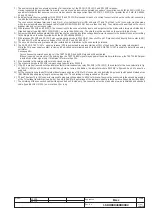
A) The circuit-breaker is only fitted with the accessories specified in the ABB SACE order acknowledgement. Consult this catalogue for information
on how to make out an order.
B) The undervoltage release is supplied for operation using a power supply branched on the supply side of the circuit-breaker or from an
independent source. The circuit-breaker can only close when the release is energized (there is a mechanical lock on closing).
If the same power supply is used for the closing and undervoltage releases and the circuit-breaker is required to close automatically when
the auxiliary power supply comes back on, a 30 ms delay must be introduced between the undervoltage release accept signal and the
energizing of the closing release. This may be achieved using an external circuit comprising a permanent make contact, the contact shown
in fig. 12 and a time-delay relay.
E) For the EIA RS485 serial interface connection see document RH0298 regarding MODBUS communication.


