L2234
Emax
69/158
Model
Scale
Page No.
Doc. No.
Apparatus
1SDH000460R0002
L2778
Failure to comply with the setting limits for “
I
1
” and “
I
n
N” can cause circuit-breaker damage with consequent
risks even for the operator.
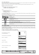
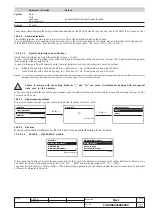
13.5.4.3 Mains frequency settings
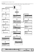
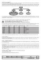
In the mains frequency menu, you can choose between the frequency values: 50, 60Hz.
2/8
50 Hz
Main Frequency
Modules
Circuit Breaker
Settings
Password
Enter password
0***
1/2
4 P
60 Hz
50 Hz
Mains Frequency
13.5.4.2
Neutral adjustment
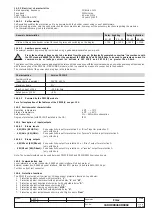
The neutral protection is normally set to a current value 50% of the adjustment made on the phases.
In some installations, where particularly high harmonics occur, the current circulating on the neutral may be higher than that of the phases.
In the SACE PR122/P release, this protection can be set for the following values: I
n
N= 50% - 100% - 150% - 200% * I
n
.
13.5.4.2.1
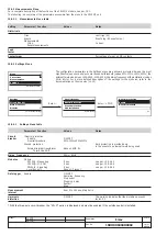
Neutral adjustment specifications
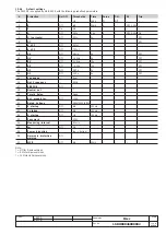
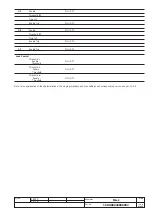
Parameter / Function
Values
System
Date
Time
Language
English/Italiano/Français/Deutsch/Español
New password
Display
Contrast
The summary table relates to the surfing of the pages dedicated to the PR120/K module (see par. 15.3) and to the PR021/K unit (see par. 16.1).
Enter
↵
Enter
↵
In any case, the relay records any setting error between I
1
and the Neutral setting and it signals this by means of the warning (see par. 13.6.3).
For four-pole CBs only.
13.5.4.4
Modules
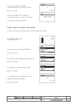
When you access the Settings menu, there is a set of menus available relating to the modules.
13.5.4.4.1
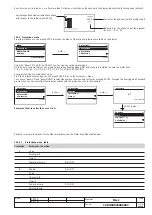
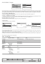
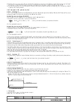
PR120/V - MEASURING module
In the measuring module you must enter a password and can then opt for the absence or presence of the voltage transformer. Moreover, you
can select the values of the primary voltage (100, 115, 120, ... 1000V) and secondary voltage (100, 110, ... 230V).
The power flow can be LOW
→
HIGH or HIGH
→
LOW. After entering a password you can choose whether the neutral connection is to be Absent
or Present. For three-pole CBs only.
1/4
Optinal modules
COM module
SIGNALLING module
MEASURING module
Modules
Module configuration
1/5
Absent
Rated voltage
Positive Power flow
Voltage Transf
MEASURING module
Neutral (InN) adjustment must meet the following formula: I
1
x I
n
N
≤
Iu.
In case of a four-pole CB, this setting is checked by the relay which signals any failure through a Led (see par. 13.6.1), and adjusts the parameter
independently to the accepted limits.
In case of a three-pole CB with external neutral, the relay performs no checks and user must correct the settings.
E.g.:
With CB E1B800 with a 400A Rating Plug, Iu = 800A and I1 = 1In, I
n
N adjustment may be: 50-100-200%.
With CB E1B800 with a 800A Rating Plug, Iu = 800A and I1 = 1In, I
n
N adjustment may be: 50-100%.
Note 1: I
1
=1l
n
setting is intended as the maximum adjustment of the protection against overloads. Actual maximum allowable adjustment must take into account any
temperature derating, terminals used and altitude, or In (rating plug)
≤
50% of circuit breaker size.

