L2234
L2778
Emax
12/158
Doc. No.
Model
Apparatus
Scale
Page No.
1SDH000460R0002
XV
2
2
3
3
4
2
4
4
6
3
6
6
2
2
3
3
4
2
4
4
6
3
6
6
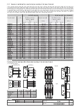
Fixed circuit-breaker terminals
No. of screws
for phase
No. of screws
for neutral
Fixed part terminals
No. of screws
for phase
No. of screws
for neutral
M12 high strength screws
Tightening torque of the main terminals: 70 Nm
5.1.3
Assembly procedure for the connection busbars
Check the state of the contact surfaces of the connections very carefully: they must be very clean with no burrs, dents or traces of rust which must
be eliminated using a fine file or an emery cloth to prevent localized increases in temperature. On completion of the operation, remove all traces
of grease or dust with a cloth soaked in a suitable solvent. When copper connections are used, it is advisable to tin-plate the contact surfaces.
When aluminium connections are used, it is advisable to apply a thin layer of Vaseline over the contact surfaces.
The connections must not exert any strain on the terminals in any direction.
Always insert a large-diameter flat washer and a spring washer between them (to spread the tightening pressure over a greater area).
Make the contact between connection and terminal and tighten the fixing screws completely.
Always use two wrenches (so as not to strain the insulating parts excessively), applying the tightening torque indicated in Fig. 18. Check tightness
after 24 hours.
Fig. 18
5.2
Earthing
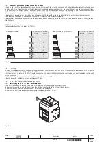
The fixed circuit-breaker and the fixed part of the withdrawable circuit-breaker have one or two terminals on the rear, marked with the special
symbol, for connection to earth (Fig. 9 and Fig. 12).
Each terminal is complete with a bolt for fixing the connection. A conductor with a cross-section conforming to current standards must be used
for the connection.
Before assembling the connection, clean and degrease the area around the screw.
After the assembly, tighten the bolt with a torque of 70 Nm.
5.3
Wiring the circuit-breaker auxiliary circuits
5.3.1
Interfacing elements for fixed circuit-breakers
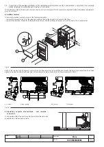
A special terminal box is provided, fitted with screw terminals for connecting the auxiliary circuits.
The terminals are marked with alphanumerical identification codes as for the electrical circuit diagram.
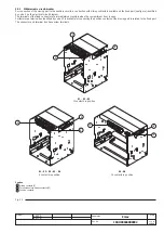
The terminal box is identified by code XV on the electrical circuit diagram.
The terminal box is immediately accessible when the compartment door is open.
Fig. 19

