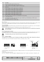
L2234
L2778
Emax
39/158
Model
Scale
Page No.
Doc. No.
Apparatus
1SDH000460R0002
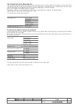
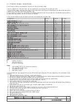
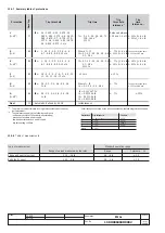
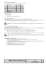
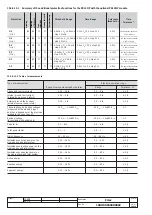
12.5.4 PR121/P default settings
The PR121/P is supplied by ABB SACE with the following preset parameters:
#
Protection
Thresholds
Time
1
L
1 In
144 s
2
S
Off
0.1 s
3
I
4 In
--
4
G
Off
0.1 s
5
Mains frequency
50 Hz
6
Neutral sel.
*
Note:
* = Off for 3-pole versions
* = 50% for 4-pole versions
* = 100% for full-size versions
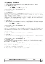
12.6 Operating instructions / Operation in service
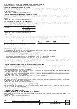
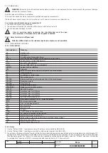
12.6.1 Neutral adjustment
The neutral protection is normally set to a current value 50% of the adjustment made on the phases.
In some installations, where particularly high harmonics occur, the current circulating on the neutral may be higher than that of the phases.
In the SACE PR121/P release, this protection can be set for the following values: I
n
N =Off - 50% - 100% - 200% * I
n
.
With three-pole circuit-breakers, without external neutral sensor, the adjustment of the neutral must be set to
OFF.
12.6.2 Neutral adjustment specifications
To adjust neutral (I
n
N) comply with the following formula: I
1
x I
n
N
≤
Iu.
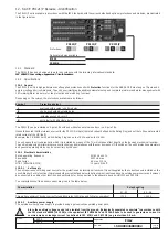
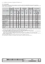
With a 4-pole CB, this setting is checked by the relay which signals any failure by means of a LED (see par. 12.7.1) and independently adjusts
this parameter, restoring it to within the accepted limits.
With a 3-pole CB, with external neutral, the relay performs no checks and setting is to be done by user.
E.g.:
With E1B800 CB having a 400A Rating Plug, Iu = 800A and I1 = 1In, I
n
N adjustment may be 50-100-200%.
With E1B800 CB having a 800A Rating Plug, Iu = 800A and I1 = 1In, I
n
N adjustment may be 50-100%.
Note 1: I
1
=1l
n
setting is intended as the maximum adjustment of the protection against overloads. Actual maximum allowable adjustment must take into account any
temperature derating, terminals used and altitude, or In (rating plug)
≤
50% of circuit breaker size.
Failure to comply with the setting limits for "I
1
"
and "I
n
N" can damage the circuit-breaker, with consequent risks to the operator
too.
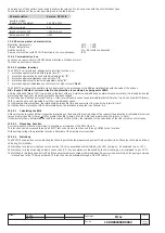
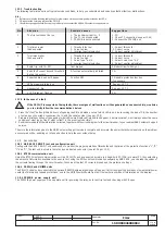
12.6.3 Replacing an electronic release
To complete the procedure for installing PR121/P take the following steps:
1.
With the circuit-breaker open and possibly disconnected, install the protection unit on the circuit-breaker.
2.
Power the unit with the PR030/B ONLY.
3.
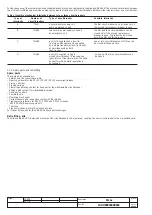
If there are no errors other than the configuration error (see par. 12.7.1), press and hold the "i Test" button for a few seconds until
all the red LEDs start to flash to confirm that installation is complete.
4.
Remove the PR030/B.
5.
Power the relay from any supply (Vaux, PR030/B, PR010/T).
6.
Make sure there are no configuration errors (“Alive” LED on).
7.
Circuit-breaker and release can now be put into service.

