Installation Sheet
November, 2016
Supersedes January 2016
s
E87010-A0105-T003-A6-CLM0
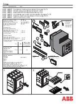
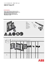
Lighting and Heating Contactor
60, 100, 200 Amp
2, 3, 4, 5 Pole
Magnetically Latched
A5E31166448A-006
Siemens Industry, Inc. 5300 Triangle Parkway, Norcross, GA 30092
Contactor Rating
Catalog Number
CLM0D... CLM0E... CLM0F...
Cont. Current Rating, Amp.
200
100
60
Tungsten
Max. Volts, line-line
480
480
480
Max. Volts, line-Neutral
277
480
277
480
480
277
Ballast
Max. Volts, line-line
Max. Volts, line-Neutral
346
600
600
600
346
600
600
Heating
Max. Volts, line-line
600
600
600
Max. Volts, line-Neutral
346
30
480
277
600
346
600
346
30
480
277
600
346
600
30
480
277
600
346
600
346
600
600
600
600
346
Table 1
Theory of Operation
Each contactor contains a permanent magnet built into its struc-
ture that will maintain the contactor in its energized state indefi
-
nitely without using control power. When energized, DC voltage
is applied to produce a magnetic field that reinforces the polarity
of the permanent magnet and the contactor closes. Immediately,
the current to the coil is disconnected by the coil clearing aux-
iliary contact. In order to open the contactor, it is necessary to
create a field through the OFF coil in the reverse direction to the
permanent magnet. This momentarily cancels the magnetic at-
traction and the contactor drops out.
Each CLM contactor has an electronic control module
“CLMKCMR” which is used to energize and close the contactor
and for the release circuit. It is designed for short time actuation
of 1-3 cycles only. All coils are designed with a small wattage
resistor in addition to a diode at coil voltages higher than 120
volts.
Remote solid state switching devices have ‘off state’
leakage currents. They may also pass utility transient voltages
through to the device electronics.
Magnetically latched CLM lighting and heating contactors can
control tungsten, fluorescent and metal vapor lamp or heating
loads. (Table 1 below shows the voltage and current rating for
various loads). Each contactor and its associated load should be
protected against short circuits by a suitable branch circuit pro-
tective device selected in accordance with the National Electric
Code (NEC).
Description
The low level ‘off state’ voltages are insufficient to actuate
the contactor but large enough to burn out the resistors.
Normal actuating voltages are quickly disconnected from
the coils and control module by the latch clearing contacts.
Coil and module failures are possible when used
with solid
state relays and PLC outputs. 24-volt systems are ok to use,
but 120 volts and above should be discouraged. If higher
voltages cannot be avoided, an interposing relay should be
used.
Care should be taken when servicing that leads do not be-
come changed from their factory installed terminals, or im
-
proper operation and possibly permanent damage to the
contactor could result.
Table 1 -
This industrial type contactor is designed to be installed, operated, and
maintained by adequately trained personnel. These instructions do not cover all
the variations of all of the topics covered herein. Contact your local sales office if
you have questions regarding the product.
CAUTION -
Device sensitive to current polarity.
Risk of damage to this device.
Do not apply AC voltage directly to the coil terminals of this device!
The permanent magnet will be demagnetized and the rectifier will be
damaged if alternating current or wrong polarity direct current is applied
directly to the coil.
CAUTION -
High inrush.
Can cause damage to this device.
Avoid attempting to manually latch or delatch the contactor.