Siemens ANSI/UL 1066, Application Manual
Siemens ANSI/UL 1066 Application Manual is a comprehensive guide for the installation and operation of Siemens' state-of-the-art electrical equipment. This indispensable manual provides in-depth instructions and valuable insights for various applications. Download your free copy now from our website to ensure optimal performance and safety.
Share
Download


Reviews:
No comments
Related manuals for ANSI/UL 1066

BRCAFLOFF
Brand: Eaton Pages: 4
eVD4
Brand: ABB Pages: 72
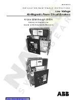
K-Line 1600A
Brand: ABB Pages: 36

AC500 V3
Brand: ABB Pages: 1029

Entelliguard G Env1
Brand: ABB Pages: 27
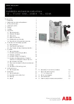
HD4-HPA Series
Brand: ABB Pages: 36

HD4/R
Brand: ABB Pages: 38

FSK II S +
Brand: ABB Pages: 36

20
Brand: ABB Pages: 15

5HK Series
Brand: ABB Pages: 16

VHK-R
Brand: ABB Pages: 16

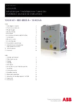
VHK 20
Brand: ABB Pages: 34

VM1
Brand: ABB Pages: 60

GCE7002270R0107
Brand: ABB Pages: 24
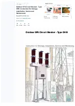
OHB
Brand: ABB Pages: 35

15VHK1200
Brand: ABB Pages: 14

ESB303
Brand: Camtec Pages: 6

T734F100EBD
Brand: Bticino Pages: 12


