ABB AC500 V3, Hardware Manual
The ABB AC500 V3 is a versatile programmable logic controller designed for automation and control applications. For comprehensive understanding of its hardware functions, refer to the detailed Hardware Manual available for free download on our website. Get your hands on this essential manual and unleash the power of your AC500 V3!
Share
Download


Reviews:
No comments
Related manuals for AC500 V3

61-059
Brand: IDEAL Pages: 2

NXBLE-125
Brand: CHINT Pages: 8

ECONOMY SMART PC-FU/DC24
Brand: Block Pages: 4

BBA 16 Series
Brand: Eaton Pages: 3

DILM95-XSP
Brand: Eaton Pages: 3

T7-T7M-X1
Brand: ABB Pages: 12

SACE Tmax T6
Brand: ABB Pages: 5
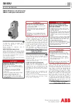
S800U
Brand: ABB Pages: 2
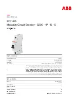
S201-K5
Brand: ABB Pages: 6

Record Plus FB100
Brand: ABB Pages: 4
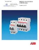
S 280 UC Series
Brand: ABB Pages: 16
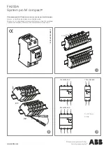
FH200A
Brand: ABB Pages: 2

F204 125 Series
Brand: ABB Pages: 2

Infinity NE-S
Brand: ABB Pages: 11

GE Power Break II GEH6271
Brand: ABB Pages: 10

Emax Series
Brand: ABB Pages: 10

K-Line Plus KDP-16
Brand: ABB Pages: 26

HPA 12kV
Brand: ABB Pages: 29


