background image

Medium voltage products
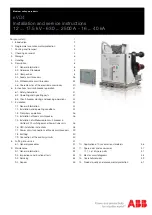
eVD4

Installation and service instructions 

12 ... 17.5 kV - 630 ... 2500 A - 16 ... 40 kA

For your safety!  

1

  I.   Introduction  

2

  II.   Programme for environmental protection  

2

  1.   Packing and transport  

3

  2.   Checking on receipt  

4

  3.   Storage  

6

  4.   Handling  

7

  5.   Description  

8

    5.1.  General information 

8

    5.2.  Reference Standards  

8

    5.3.  Composition  

8

    5.4.  Fixed circuit-breakers  

26

    5.5.  Withdrawable circuit-breakers 

32

    5.6.  Characteristics of the electrical accessories  

40

  6.  Instructions for circuit-breaker operation 

41  

    6.1.  Safety indications 

41

    6.2.  Operating and signalling parts 

41

    6.3.  Circuit-breaker closing and opening operations 

42

  7.   Installation  

44

    7.1.  General information  

44

    7.2.  Installation and operating conditions 

44

    7.3.  Preliminary operations 

 46

    7.4.  Installation of fixed circuit-breaker  

46

    7.5. Installation of withdrawable circuit-breaker in  


UniGear ZS1 switchgear and PowerCube units 

46

    7.6.  HMI installation instructions 

48

    7.7.  Power circuit connections of fixed circuit-breakers   49
    7.8.  Earthing  

50

    7.9.  Connection of the auxiliary circuits 

50

  8.   Putting into service  

51

    8.1.  General procedures  

51

  9.   Maintenance  

52

    9.1.  General information  

52

    9.2.  Inspections and functional tests  

52

    9.3.  Servicing  

54

    9.4.  Repairs  

55

 10.   Application of X-ray emission standards 

56

 11.   Spare parts and accessories 

57

    11.1. List of spare parts  

57

 12.   Electric circuit diagrams  

58

 13.   Overall dimensions  

59

 14.   Product quality and environmental protection 

67


Summary of Contents for eVD4

Page 1: ...erations 42 7 Installation 44 7 1 General information 44 7 2 Installation and operating conditions 44 7 3 Preliminary operations 46 7 4 Installation of fixed circuit breaker 46 7 5 Installation of withdrawable circuit breaker in UniGear ZS1 switchgear and PowerCube units 46 7 6 HMI installation instructions 48 7 7 Power circuit connections of fixed circuit breakers 49 7 8 Earthing 50 7 9 Connectio...

Page 2: ......

Page 3: ...he installations conform to the rules of good working practice and safety in the work pace Strictly follow the information given in this instruction manual Check that the rated performance of the apparatus is not exceeded during service Check that the personnel operating the apparatus have this instruction manual to hand as well as the necessary information for correct intervention Pay special att...

Page 4: ...ection coordination studies etc especially regarding any variants requested in relation to the standardised configurations Only use original spare parts for maintenance operations For further information please also see the technical catalogue of the circuit breaker and the spare parts catalogue All the installation putting into service running and maintenance operations must be carried out by ski...

Page 5: ...is shipped in special packing in the open position and with the spring released Each piece of apparatus is protected by a plastic cover to prevent water from infiltrating during the loading and unloading stages and to keep the dust off during storage ...

Page 6: ... manual this document test certification identification label copy of the shipping documents electric wiring diagram Other documents which are sent prior to shipment of the apparatus are order confirmation original shipping advice note any drawings or documents referring to special configurations conditions CIRCUIT BREAKER eVD4 P 12 06 25 CLASSIFICATION M2 SN 1VC1BA00045139 M WEIGHT 124 kg Ur VOLT...

Page 7: ... Feeder 3 C Motor 1 G Motor 2 H Full functionality Z Communication module type Two channel Ethernet A Two channel serial B Two channel optic fibre C None N CB type Fixed F Withdrawable manual truck W Withdrawable motorized truck M Rated current of sensors Combisensor C Current sensor I Voltage range LV 48 60 V dc L HV 110 250 V dc H Sensor type K1 250 A A K2 K3 500 A B RL1 presence NO N Yes L RL2 ...

Page 8: ...t be packed again with the original material supplied Insert packets of special hygroscopic substances inside the packing with at least one standard packet for piece of apparatus If immediate installation is not possible store the apparatus in a covered well ventilated dry dust free non corrosice place well away from any easily flammable materials and at a temperature between 5 C and 40 C for lowe...

Page 9: ...ing tool 1 not supplied fitted with ropes with safety hooks 2 insert the hooks 2 in the supports 3 fixed to the frame of the circuit breaker and lift Put the hooks 2 into the support holes 3 according to the type of apparatus see table on completion of the operation and in any case before putting into service unhook the lifting tool 1 and dismantle the supports 3 from the frame During handling tak...

Page 10: ...5 3 Composition The eVD4 circuit breaker is a system consisting of vacuum circuit breaker with mechanical stored energy and free release operating mechanism 5 RBX615 electronic unit to carry out the protection control measurement monitoring and self diagnosis functions 3 embedded sensors for current and voltage measurement 2 Human Machine Interface HMI allowing all the RBX615 functions to be manag...

Page 11: ...ck in the open position on request 8 Padlock in the open position on request 9 Connector Plug 10 Pushbutton protection on request 11 M12 fixing devices 250x400 12 Earth terminal M12 13 Electronics 14 Current and voltage sensors 15 Motorized truck on request for UniGear panels 16 Centring pins 17 Signalling LED 18 Slides for operating the switchgear shutters 19 Locks for hooking into the fixed part...

Page 12: ...c properties being restored 1 Upper terminal 2 Vacuum interrupter 3 Housing pole 4 Stem of moving contact 5 Lower terminal 6 Flexible connection 7 Tie rod spring fork 8 Tie rod 9 Pole fixing 10 Connection to operating mechanism Vacuum interrupter embedded in the pole 1 Terminal 2 Protection 3 Metal bellows 4 Interrupter housing 5 Shield 6 Ceramic insulator 7 Shield 8 Contacts 9 Terminal 10 Interru...

Page 13: ...t and voltage trends during a single phase vacuum interruption process Radial magnetic field contact arrangement with a rotating vacuum arc Recovery voltage system frequency Transient recovery voltage TRV high frequency Time Current Voltage System voltage Contact separation Arc voltage Short circuit current interruption Current of short circuit Spiral geometry of ABB interrupter contacts The speci...

Page 14: ...nstallations to be inspected whilst guaranteeing maximum operator safety Key locks or padlocks enable opening and closing operations and or racking in and racking out The racking out device with the door closed only allows the circuit breaker to be racked into or out of the switchgear only with the door closed Anti racking in locks prevent circuit breakers with different rated currents from being ...

Page 15: ...dimensions better performance compared to traditional current and voltage transformers and a higher degree of standardization 5 3 6 1 Rogowski coils A uniform winding on a closed circular support with a constant cross section and without the ferromagnetic core The voltage induced in the winding is directly proportional to the let through current variation There are many advantages provided by usin...

Page 16: ...e circuit breaker bushing The output signal is a voltage directly proportional to the primary voltage The voltage sensors are characterized by absence of any ferroresonance phenomena and their insensitivity to the effects of the direct components A single divider covers the service range of voltages up to the rated voltage of the circuit breaker 5 3 6 3 Types and characteristics of the sensors use...

Page 17: ...n against short circuit directional and non directional protection overcurrent protection with definite delay trip and protection against thermal overload It also has a directional and non directional earth fault protection a protection against sensitive earth fault SEF and a protection against earth fault with measurement of the transients including detection of intermittent earth faults in wired...

Page 18: ...onitoring of the protection relays and their GOOSE communication by means of the station bus Separate physical wiring is not required for horizontal communication among the switchgear units 5 3 7 4 Preventive status monitoring To guarantee operative availability of the protection the RBX615 relay includes a wide range of monitoring functions to supervise the hardware and software communication the...

Page 19: ...y outputs that can be freely programmed by the user plus a further 7 inputs and 6 outputs assigned to predefined functions The binary inputs and outputs of the relay are available in the low voltage compartment of the switchgear by means of the circuit breaker plug socket contacts eVD4 makes three communication modules Ethernet RJ45 electrical communication RS485 serial electrical communication Et...

Page 20: ...shold EFLPTOC1 I0 1 51N 1 1 EFLPTOC2 I0 2 51N 1 2 Earth fault non directional second threshold EFHPTOC1 I0 1 51N 2 1 Earth fault non directional third threshold EFIPTOC1 I0 1 50N 51N 1 Earth fault directional first threshold DEFLPDEF1 I0 1 67N 1 1 DEFLPDEF2 I0 2 67N 1 2 Earth fault directional second threshold DEFHPDEF1 I0 67N 2 Protection against reverse sequence overcurrent NSPTOC1 I2 1 46 1 NSP...

Page 21: ...CM CBCM Supervision of the state of the shunt opening release OCSSCBR1 TCS Open TCM Open Supervision of the state of the shunt closing release CCSSCBR1 TCS Close TCM Close Monitoring of fuse fault SEQRFUF1 FUSEF 60 Counter of the overall duration of starting MDSOPT1 OPTS OPTM Measurement Disturbance recorder RDRE1 Measurement of three phase currents CMMXU1 3I 3I Measurement of current sequence CSM...

Page 22: ... contains the following parts Display Pushbuttons LED indicators Communication port USB port reserved for Service Housing for SD memory reserved for future applications Wireless adapter reserved for future applications 5 3 7 12 LCD Display The local HMI locale LHMI includes a graphic display which supports two character sizes according to the language selected The number of characters and lines di...

Page 23: ...irectly during display of another menu Display the default screen of the main menu R L Change the RBF615 control mode remote or local When the R LED is on remote control is enabled and local control is disabled When the LED L is on local control is enabled and remote control is disabled When no LED is on both the controls are enabled Cancel Activates the Clear Reset screen Cancel indications and L...

Page 24: ...ee LEDs for indicating the state of the protections and of the relay functions A further 8 alarm LEDs are available on the front of the LHMI By means of these 8 LEDs it is possible to display the state of 24 alarms organized into three pages The Alarm page button allows switching among the various LED pages These LEDs can be configured by means of PCM600 LHMI functions Protection and alarm indicat...

Page 25: ...eans of the LHMI For the change to become effective the IED must be restarted The WHMI offers the following functions Alarm notifications and list of events Supervision of the system Configuration of the parameters Display of the measurements Recordings of Disturbances Disturbance recorder Phasor diagram WHMI menu tree structure The WHMI can be used Locally by connecting your laptop to the LHMI by...

Page 26: ...hanges Showing context sensitive help messages Clearing events Triggering the disturbance recorder manually Saving values to CSV file format Freezing the values so that updates are not displayed Receiving continuous updates to the monitoring view Deleting the disturbance record Deleting all disturbance records Uploading part one of a disturbance record Uploading part two of a disturbance record 5 ...

Page 27: ... the other hand for the WHMI access is always present by means of authentication The following table gives the different user profiles with their relative rights User Rights Viewer Read only access Operator Select the local or remote control mode locally Change setting group Cancel the alarm LEDs and the text notifications Engineer Configure the parameters Cancel the list of events Cancel the dist...

Page 28: ...kV 75 Rated frequency fr Hz 50 60 Rated thermal current 40 C Ir A 630 630 630 1250 1250 1250 Rated breaking capacity symmetrical rated short circuit current Isc kA 16 16 16 16 16 16 20 20 20 20 20 20 25 25 25 25 25 25 31 5 31 5 31 5 31 5 31 5 31 5 Short time withstand current 3s Ik kA 16 16 16 16 16 16 20 20 20 20 20 20 25 25 25 25 25 25 31 5 31 5 31 5 31 5 31 5 31 5 Making capacity Ip kA 40 40 40...

Page 29: ...00160 000176 5 40 1 5 4 3 Standard fittings for fixed circuit breakers The basic versions of the fixed circuit breakers are three pole and fitted with EL type manual operating mechanism mechanical signalling device for closing spring loaded released mechanical signalling device for circuit breaker open closed closing pushbutton opening pushbutton and operation counter lever for manual closing spri...

Page 30: ...and current 3s Ik kA 16 16 16 16 16 16 20 20 20 20 20 20 25 25 25 25 25 25 31 5 31 5 31 5 31 5 31 5 31 5 Making capacity Ip kA 40 40 40 40 40 40 50 50 50 50 50 50 63 63 63 63 63 63 80 80 80 80 80 80 Sequence of operations O 0 3 s CO 15 s CO Opening time ms 33 60 Arcing time ms 10 15 Total breaking time ms 43 75 Closing time ms 60 80 Maximum overall dimensions H mm 461 461 461 461 461 461 W mm 450 ...

Page 31: ...25 31 5 31 5 31 5 31 5 31 5 40 40 40 40 40 40 50 50 50 50 50 63 63 63 63 63 80 80 80 80 80 100 100 100 100 100 100 33 60 10 15 43 75 60 80 589 589 599 599 589 589 599 599 599 570 700 570 700 570 700 570 700 700 483 483 483 483 483 483 483 483 483 210 275 210 275 210 275 210 275 275 84 84 98 105 84 84 98 105 160 000161 000162 000159 000160 000161 000162 000159 000160 000176 5 40 1 ...

Page 32: ... 1250 eVD4 12 12 40 p210 20 1600 eVD4 12 16 20 p210 25 1600 eVD4 12 16 25 p210 31 5 1600 eVD4 12 16 32 p210 40 1600 eVD4 12 16 40 p210 20 2000 eVD4 12 20 20 p210 25 2000 eVD4 12 20 25 p210 31 5 2000 eVD4 12 20 32 p210 40 2000 eVD4 12 20 40 p210 16 630 eVD4 12 06 16 p275 20 630 eVD4 12 06 20 p275 25 630 eVD4 12 06 25 p275 31 5 630 eVD4 12 06 32 p275 16 1250 eVD4 12 12 16 p275 20 1250 eVD4 12 12 20 ...

Page 33: ...p210 40 1250 eVD4 17 12 40 p210 20 1600 eVD4 17 16 20 p210 25 1600 eVD4 17 16 25 p210 31 5 1600 eVD4 17 16 32 p210 40 1600 eVD4 17 16 40 p210 20 2000 eVD4 17 20 20 p210 25 2000 eVD4 17 20 25 p210 31 5 2000 eVD4 17 20 32 p210 40 2000 eVD4 17 20 40 p210 16 630 eVD4 17 06 16 p275 20 630 eVD4 17 06 20 p275 25 630 eVD4 17 06 25 p275 31 5 630 eVD4 17 06 32 p275 16 1250 eVD4 17 12 16 p275 20 1250 eVD4 17...

Page 34: ...truck The circuit breaker is completed with the isolating contacts 21 Circuit breaker eVD4 P 12 Standards IEC 62271 100 VDE 0671 CEI EN 62271 100 file 7642 Rated voltage Ur kV 12 Rated insulation voltage Us kV 12 Withstand voltage at 50 Hz Ud 1 min kV 42 Impulse withstand voltage Up kV 75 Rated frequency fr Hz 50 60 Rated thermal current 40 C 1 Ir A 630 1250 1250 1250 Rated breaking capacity symme...

Page 35: ...couplings of the switchgear The locks can only be activated by the handles with the truck fully resting against the crosspiece The operating lever 22 must be fully inserted also see par 7 5 A lock prevents the truck from advancing into the enclosure or fixed part when the earthing switch is closed Another lock prevents racking in and racking out with the circuit breaker closed With the truck in an...

Page 36: ...6 20 20 25 25 31 5 31 5 40 40 Making capacity Ip kA 40 40 50 50 63 63 80 80 100 100 Sequence of operations O 0 3 s CO 15 s CO Opening time ms 33 60 Arcing time ms 10 15 Total breaking time ms 43 75 Closing time ms 60 80 Maximum overall dimensions H mm 628 628 691 691 W mm 503 503 653 853 D mm 662 662 641 642 Pole centre distance P mm 150 150 210 275 Weight kg 116 116 174 176 Standardized dimension...

Page 37: ... 20 20 20 25 25 25 25 25 31 5 31 5 31 5 31 5 31 5 40 40 40 40 40 50 50 50 50 50 63 63 63 63 63 80 80 80 80 80 100 100 100 100 100 33 60 10 15 43 75 60 80 691 691 691 691 691 691 691 653 853 653 853 653 853 853 640 640 641 641 640 640 640 210 275 210 275 210 275 275 160 166 174 176 160 166 221 000164 000165 000166 000167 000164 000165 000175 5 40 2 ...

Page 38: ...12 16 25 p210 31 5 1600 eVD4 P 12 16 32 p210 40 1600 eVD4 P 12 16 40 p210 20 2000 eVD4 P 12 20 20 p210 25 2000 eVD4 P 12 20 25 p210 31 5 2000 eVD4 P 12 20 32 p210 40 2000 eVD4 P 12 20 40 p210 40 1250 eVD4 P 12 12 40 p275 20 1600 eVD4 P 12 16 20 p275 25 1600 eVD4 P 12 16 25 p275 31 5 1600 eVD4 P 12 16 32 p275 40 1600 eVD4 P 12 16 40 p275 20 2000 eVD4 P 12 20 20 p275 25 2000 eVD4 P 12 20 25 p275 31 ...

Page 39: ...4 P 17 16 25 p210 31 5 1600 eVD4 P 17 16 32 p210 40 1600 eVD4 P 17 16 40 p210 20 2000 eVD4 P 17 20 20 p210 25 2000 eVD4 P 17 20 25 p210 31 5 2000 eVD4 P 17 20 32 p210 40 2000 eVD4 P 17 20 40 p210 40 1250 eVD4 P 17 12 40 p275 20 1600 eVD4 P 17 16 20 p275 25 1600 eVD4 P 17 16 25 p275 31 5 1600 eVD4 P 17 16 32 p275 40 1600 eVD4 P 17 16 40 p275 20 2000 eVD4 P 17 20 20 p275 25 2000 eVD4 P 17 20 25 p275...

Page 40: ...00 100 100 100 Sequence of operations O 0 3 s CO 15 s CO Opening time ms 33 60 33 60 33 60 Arcing time ms 10 15 10 15 10 15 Total breaking time ms 43 75 43 75 43 75 Closing time ms 60 80 60 80 60 80 Maximum overall dimensions H mm 621 621 691 691 691 691 691 W mm 503 503 653 653 653 653 853 D mm 662 662 641 640 641 640 640 Pole centre distance P mm 150 150 210 210 210 210 275 Weight kg 116 116 174...

Page 41: ...40 40 40 40 Making capacity Ip kA 40 40 50 50 50 50 50 63 63 63 63 63 80 80 80 80 80 100 100 100 100 Sequence of operations O 0 3 s CO 15 s CO Opening time ms 33 60 33 60 33 60 Arcing time ms 10 15 10 15 10 15 Total breaking time ms 43 75 43 75 43 75 Closing time ms 60 80 60 80 60 80 Maximum overall dimensions H mm 621 621 691 691 691 691 691 W mm 503 503 653 653 653 653 853 D mm 662 662 641 640 6...

Page 42: ...0 V d c Type HV 110 250 V d c Operating limits 75 110 Un Inrush power Ps 60 W Inrush time 400 ms Continuous power consumption Pc 15 W Relay power on release impulse 150 W Insulation voltage 2 kV Electric I O characteristics see technical manual Shunt opening release MBO1 Shunt closing release MBC Un Depending on the power supply voltage of the RBX615 relay Opening time 35 60 ms Closing time 40 70 ...

Page 43: ...ts seat Should mechanical operations be carried out on the circuit breaker outside the switchgear take great care of the moving parts If the operations are prevented do not force the mechanical interlocks and check that the operating sequence is correct Racking the circuit breaker in and out of the switchgear must be done gradually to avoid shocks which may deform the mechanical interlocks 6 2 Swi...

Page 44: ...starts reloading the springs again when the power returns In any case it is always possible to complete the loading operation manually c Circuit breaker closing c1 Circuit breaker closing from the front The operation can only be carried out with the closing spring completely loaded For manual closing press the button 5 fig 6a When there is a shunt closing release the operation can also be carried ...

Page 45: ...rried out the instructions in points a b c and d comply with the following indications to open the circuit breaker e select SLD with the SLD button f select the circuit breaker by means of the arrow buttons g press the red O button to open the circuit breaker h confirm the opening operation with the enter arrow button The circuit breaker will open and this will be indicated by the SLD and by the L...

Page 46: ...erage value of the relative humidity measured for a period longer than 1 month must not exceed 90 The average value of the pressure of the water vapour measured for a period longer than 1 month must not exceed 1 8 kPa Altitude 1000 m above sea level 7 2 2 Special operating conditions Installation over 1000 m a s l Possible within the limits permitted by reduction of the dielectric resistance of th...

Page 47: ...45 45 eVD4 N eVD4 N eVD4 N eVD4 Fig 8b Fig 8c Fig 8d Fig 8e ...

Page 48: ... breaker installation operations also refer to the technical documentation of the above mentioned switchgear The racking in out operations must always be carried out with the circuit breaker open When putting into service for the first time it is advisable to charge the circuit breaker operating mechanisms manually so as not to overload the auxiliary power supply circuit 7 5 1 Circuit breakers wit...

Page 49: ...gside L comes on a Select the Single Line Diagram section SLD by means of the SLD button the top bar of the display shows the part dedicated to the SLD it turns black b When the SLD is selected use the up and down arrow buttons to select the truck symbol Racking in Racking out Fig 9 c when the Truck is selected press the red opening button to rack in the circuit breaker d Confirm the racking in co...

Page 50: ...ble the two pole power supply connector of the HMI XDB32 Note The HMI can be supplied both in direct current and in alternating current V 48 250 V d c a c The racking in operation can only be carried out with the circuit breaker open Note Make sure that the control mode is set to Local the LED alongside the letter L on button must be on otherwise press the control mode selection button until the L...

Page 51: ...rfaces of the lubricated heads Take into ac count the deviations from the general Standards table for example for systems in contact or terminals as foreseen in the specific technical documentation The thread and contact surfaces of the bolt heads must be slightly oiled or greased so as to obtain a correct nominal tightening torque 7 7 Power circuit connections of fixed circuit breakers 7 7 1 Gene...

Page 52: ...tion of the panel wiring part It consists of 58 pin socket pre engineered for Ethernet electric ports 1 Cables 1 5 metres long with 2 5 mm2 cross section copper cables for the power connections and with 1 mm2 cross section for the signal connections Serial cable 1 5 m long for the signal connection with the HMI fitted with special connector on the end 2 2 Ethernet connection modules 1 5 m long wit...

Page 53: ...ered check that the ready LED both on the RBX615 unit and on the HMI is on The LEDs are on and not flashing 4 Manual operating mechanism Carry out a few closing and opening operations both from the front of the circuit breaker and from HMI see chap 6 N B If these applications are present make sure that the locking magnet on the operating mechanism RLE1 is energized and that the undervoltage releas...

Page 54: ...ctly executed it is possible to carry out up to 1000 racking out in operations as prescribed in the IEC 60271 200 Standards the data regarding the operating life are basically applicable to all the components which cannot be directly affected by operator activity The behaviour of manually operated components moving parts of isolatable parts etc can vary 9 2 Inspections and functional tests 9 2 1 B...

Page 55: ...Circuit breaker pole No other check is necessary except what has already been specified in par 9 2 1 Fig 12 9 2 4 Withdrawable assembly truck and circuit breaker Visually inspect the components especially those which may be damaged by incorrect operations also see table in chap 8 Visually inspect the isolating contacts and make sure that all the contact parts are clean especially in cases where si...

Page 56: ...tact the ABB Service office Complete replacement of the actuator shock absorber and of the other transmission system parts shaft main levers safety rings etc must be carried out after 30 000 operations Circuit breakers up to 40 kA and up to 2500 A To ensure correct operation of the circuit breaker inspection and maintenance of the tripping devices is recommended every 10 000 operations For this pu...

Page 57: ...the power supply off and make the working area safe by following the safety regulations specified in the IEC DIN VDE Standards remove the RBX615 device see paragraph 5 3 7 open the circuit breaker earth a terminal of each circuit breaker pole connect the earth terminal of the VIDAR tester to the circuit breaker structure connect the high voltage terminal of the VIDAR tester to the terminal of the ...

Page 58: ...rating mechanism and by the adjustments of the transmission system One of the physical properties of vacuum insulation is the possibility of X ray emission when the interrupter contacts are open The specific tests carried out at the PTB laboratories Physikalisch Technische Bundesanstalt in Brunswick Germany show that local emission at a distance of 10 cm from the interrupter or pole surface does n...

Page 59: ...ng sales codes indicated in the technical catalogue and always state the following type of circuit breaker rated voltage of the circuit breaker rated thermal current of the circuit breaker breaking capacity of the circuit breaker serial number of the circuit breaker rated voltage of any electrical spare parts For availability and to order spare parts please contact our Service office 11 1 List of ...

Page 60: ...with the standard electric circuit diagram or with a specific diagram in the case of a circuit breaker with non standard wiring The standard eVD4 circuit breaker electric circuit diagrams are as follows 1VCD400137 Fixed circuit breakers 1VCD400106 Withdrawable circuit breakers ...

Page 61: ... 217 5 409 32 115 77 5 424 45 250 114 56 12 22 PROF 18 45 10 12 PROF 25 2xM M 22 12 150 150 22 161 1 12 49 248 450 435 28 170 16 56 31 400 25 236 28 40 A 25 520 296 475 45 461 56 31 49 16 308 570 28 28 435 170 22 12 22 PROF 25 45 M 2xM10 PROF 20 115 77 5 217 5 114 424 95 409 205 25 250 32 12 210 160 22 210 12 A A 59 13 Overall dimensions Fixed circuit breakers Fixed circuit breakers ...

Page 62: ...2 M 22 PROF 25 2xM10 PROF 18 A A 59 310 475 602 296 25 520 deep 20 10 5 2 p e e d 2 1 M x 4 M x 2 409 77 5 32 45 424 12 95 250 24 237 5 16 308 31 170 28 56 570 49 28 435 210 22 210 12 160 20 20 12 20 20 12 A A 59 Fixing interchangeability with the previous series 345 x 650 Fixed circuit breakers Fixed circuit breakers eVD4 TN 1VCD000159 Ur 12 kV 17 5 kV Ir 1600 A 2000 A Isc 20 kA 25 kA 31 5 kA 40 ...

Page 63: ...0 20 4xM12 12 20 PROF 25 12 2xM10 PROF 20 49 700 373 31 650 361 16 28 28 435 56 25 170 32 95 250 114 12 409 424 45 78 24 238 275 22 213 12 275 20 20 A A 59 x18 deep 10 M M12x25 deep 589 310 250 114 475 45 520 296 11 11 11 11 77 5 238 32 95 12 430 24 409 210 210 22 12 160 308 28 170 56 16 31 49 570 28 435 A A 59 Fixed circuit breakers Fixed circuit breakers ...

Page 64: ... 49 28 435 56 170 700 373 16 31 28 36 275 22 275 12 213 A A 59 602 475 12 12 20 20 2xM10 PROF 20 4xM12 PROF 25 VISTA A SCALA 1 2 20 20 275 275 22 12 213 A 45 12 409 78 238 310 32 424 59 114 250 24 95 170 373 700 16 56 31 49 28 650 28 361 25 435 eVD4 TN 1VCD000176 Ur 12 kV 17 5 kV Ir 2500 A Isc 20 kA 25 kA 31 5 kA 40 kA Fixed circuit breaker Fixed circuit breaker ...

Page 65: ...28 14 56 49 503 213 31 36 1250A 98 636 44 4 688 691 213 16 56 30 14 653 36 28 49 28 230 310 320 359 5 25 19 5 76 165 62 5 10 688 303 71 38 122 21 5 640 53 466 383 370 79 4 280 111 36 108 210 210 550 626 640 650 173 38 53 587 55 173 Withdrawable circuit breakers for UniGear ZS1 switchgear and PowerCube units Withdrawable circuit breakers for UniGear ZS1 switchgear and PowerCube units eVD4 P TN 1VCD...

Page 66: ...53 587 38 806 836 44 636 14 653 4 688 691 213 16 56 30 49 28 28 36 230 310 19 5 25 320 10 688 18 21 5 280 691 122 370 76 165 641 53 466 359 5 383 71 38 62 5 303 79 4 173 111 36 210 210 550 55 111 38 650 173 53 588 626 640 Withdrawable circuit breakers for UniGear ZS1 switchgear Withdrawable circuit breakers for UniGear ZS1 switchgear and PowerCube units eVD4 P TN 1VCD000165 Ur 12 kV 17 5 kV Ir 160...

Page 67: ...75 55 111 850 53 38 173 588 806 836 230 842 853 14 4 688 691 213 16 56 30 49 28 28 36 144 19 5 25 320 10 688 21 5 76 165 370 640 152 62 5 303 38 71 359 5 383 466 53 36 310 280 4 173 111 109 850 750 275 275 55 111 173 53 38 806 836 588 eVD4 P TN 1VCD000175 Ur 12 kV 17 5 kV Ir 2500 A Isc 20 kA 25 kA 31 5 kA 40 kA Withdrawable circuit breakers for UniGear ZS1 switchgear Withdrawable circuit breakers ...

Page 68: ...66 66 74 60 89 10 160 10 58 2 106 5 58 2 17 51 180 34 5 223 HM1 ...

Page 69: ...and help with re cycling and disposal of the products at the end of their life For disposal of the products it is always necessary to act in accordance with local legal requirements in force Methods of disposal Disposal can be carried out with heat treatment in incineration plants or by means of storage in special waste sites Material Recommended disposal method Metal material Fe Cu Al Ag Zn W oth...

Page 70: ...68 68 ...

Page 71: ......

Page 72: ...P O Box 699 FI 65101 VAASA Finland Phone 358 10 22 11 Fax 358 10 22 41094 www abb com substationautomation ABB AG Calor Emag Medium Voltage Products Oberhausener Strasse 33 Petzower Strasse 8 D 40472 Ratingen D 14542 Glindow Phone 49 0 2102 12 1230 Fax 49 0 2102 12 1916 E mail powertech de abb com www abb com We reserve the right to modify the contents of this document without prior notice followi...

Reviews: