background image

—  VD4X

Vacuum circuit-breaker

I N S T R U C T I O N   M A N U A L

VD4X

Vacuum circuit-breaker

Summary of Contents for VD4X

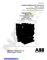
Page 1: ... VD4X Vacuum circuit breaker INSTRUCTION MANUAL VD4X Vacuum circuit breaker ...

Page 2: ......

Page 3: ...28 Summary Technical data Structure and mode of action Commissioning Operation Maintenance Application of the X ray regulations Comparison of designations to IEC 81346 1 IEC 81346 2 IEC 61346 1 IEC 61346 2 and VDE DIN 40719 Part 2 Content ...

Page 4: ...rning symbol Ensure that the technical data in the specifica tion are not exceeded during operation of the switching device or switchgear The instruction manual must be kept accessible to all persons entrusted with work on the switching device It is to be ensured that the number of the instruction manual used is iden tical with the number on the type plate of the circuit breaker The user s personn...

Page 5: ...er installations with rated voltages above 1 kV Accident prevention regulations issued by the appropriate professional bodies or comparable organizations Safety guidelines for auxiliary and operating materials Order related details provided by the switchgear manufacturer 1 3 Operating conditions 1 3 1 Normal operating conditions Design to IEC 62271 1 High voltage switchgear and controlgear Part 1 ...

Page 6: ...1 2425 31 3612 31 3625 31 3625 40 4012 31 4025 31 4025 40 Rated Voltage kV 12 12 17 5 24 24 36 36 36 40 5 40 5 40 5 Rated current A 1250 1600 2500 1250 1250 1600 2500 1250 2500 1250 2500 1250 2500 2500 Rated short circuit breaking current symm 8 kA 31 5 31 5 31 5 31 5 31 5 31 5 31 5 40 31 5 31 5 40 Rated short circuit making current peak 8 kA 80 80 80 80 80 80 80 100 80 80 100 Rated short circuit ...

Page 7: ...70 ms 30 45 ms 27 45 ms 2 15 ms 60 ms 20 ms 120 ms 1 20 ms 80 ms 1 2 2 Technical data Equipment 2 2 1 Charging motor for stored energy spring mechanism Supply voltage V AC V DC Motor protection ABB Stotz Automat A 1 60 S 281 UC K 1 60 0 75 0 75 6 00 S 282 UC K 6 00 4 00 3 00 1 60 1 60 0 75 0 75 Power consumption approx 260 VA 3 approx 200 260 W 3 Charging time maximum 2 s 15 15 15 15 15 15 15 15 1...

Page 8: ...X pole side Figure 2 1c Vacuum circuit breaker type VD4X mechanism side with front plate Figure 2 1d Vacuum circuit breaker type VD4X pole side Figure 2 1e Vacuum circuit breaker type VD4X mechanism side with front plate Figure 2 1f Vacuum circuit breaker type VD4X pole side Figure 2 1a Figure 2 1b Figure 2 1c Figure 2 1d Figure 2 1e Figure 2 1f ...

Page 9: ... 3 4 5 6 7 8 10 5 2 3 4 5 6 7 8 10 9 20 30 40 50 10 0 05 5 0 1 0 2 0 3 0 4 0 5 0 6 0 8 1 6 7 8 10 2 3 4 5 6 7 8 10 2 2 3 4 5 6 7 8 10 3 2 3 4 5 6 7 8 4 2 3 4 5 6 7 8 10 5 2 3 4 5 6 7 8 10 9 20 30 40 50 10 Number of operating cycles n Breaking current Ia kA Number of operating cycles n 0 05 5 0 1 0 2 0 3 0 4 0 5 0 6 0 8 1 6 7 8 10 2 3 4 5 6 7 8 10 2 2 3 4 5 6 7 8 10 3 2 3 4 5 6 7 8 4 2 3 4 5 6 7 8 ...

Page 10: ...conductor bar A2 Front terminal for conductor bar D Pressure sensor for circuit breaker compartment F Filler connector for circuit breaker compartment K Plug Terminal for rated curreut 630 A 12 17 5 24 kV 25 kV Panel cutout View X and Y M12 25 Deep Figure 2 3 ...

Page 11: ...r for circuit breaker compartment F Filler connector for circuit breaker compartment K Plug Terminal for rated curreut 1250 A 12 17 5 kV 31 5 kV 24 kV 25 kV Panel cutout View X and Y M12 25 Deep 1 Busbar connection arranged above or bolow the breaker pole depending on the suitchgear system Figure 2 4 ...

Page 12: ...ressure sensor for circuit breaker compartment F Filler connector for circuit breaker compartment K Plug Terminal for rated curreut 1250 A 12 17 5 24 40 5 kV 31 5 kV Panel cutout View X and Y 1 Busbar connection arranged above or bolow the breaker pole depending on the suitchgear system Figure 2 5 ...

Page 13: ...r bar D Pressure sensor for circuit breaker compartment F Filler connector for circuit breaker compartment K Plug Panel cutout View X and Y 1 Busbar connection arranged above or bolow the breaker pole depending on the suitchgear system Terminal for rated current 1250 A Figure 2 6 ...

Page 14: ...25 50 120 120 74 526 10 526 84 89 127 21 83 120 62 53 8 1 8 2 2 3 8 2 3 36 17 107 8 1 5 5 2 36 61 431 104 7 232 276 5 562 1 5 130 275 1 1 130 57 2 3 2 3 57 150 150 40 20 25 50 61 125 125 125 500 10 526 83 9 21 84 89 127 21 83 46 9 62 53 8 1 8 2 2 3 8 2 3 36 17 107 8 1 5 5 2 36 61 431 104 7 50 2 562 1 5 130 275 1 1 130 57 2 3 2 3 57 150 150 40 20 25 50 A 1 Connection for conductor bar depends on sw...

Page 15: ... by a motor external activation and deactivation Emer gency manual operation with a charging lever is possible There are rating plates with the main data of the switching device at front plate 1 1 and at the right of the mounting plate 3 2 1 Operating mechanism equipment 1 Basic operating equipment Shunt release OFF Y2 Shunt release ON Y3 Mechanical ON push button 2 Mechanical OFF push button 3 Ro...

Page 16: ...tivation of the releases 1 Only shunt release OFF Y2 and Y9 and shunt release ON Y3 are provided for operational opening and closing These three releases are rotary magnets and are suitable for a high number of operating cycles 2 The undervoltage release Y4 or the indirect overcurrent release Y7 are purely safety protective tripping units and must not be used for operational switching 3 3 4 Auto r...

Page 17: ...uit breaker operating mechanism 1 1 Front plate 1 2 Bore for handling both sides 9 Mounting plate 9 1 O ring 9 2 Operating mechanism mounting 11 Insulating material pole tube 12 Breaker terminal 13 Front breaker terminal 14 Spiral spring contact 15 Vacuum interrupter 16 Contact force spring 17 Insulating push rod 18 Lock nut 18 1 Spring washer 18 2 Retaining plate 18 3 Positioning plate 18 4 Washe...

Page 18: ... Circuit breaker operating mechanism 1 1 Front plate 9 Mounting plate 9 1 O ring 9 2 Operating mechanism mounting 11 Insulating material pole half shell 12 Breaker terminal 13 Front breaker terminal 14 Flexible conductor 15 Vacuum interrupter 16 Contact force spring 17 Insulating push rod 18 Lock nut 18 1 Spring washer 18 2 Retaining plate 18 3 Positioning plate 18 4 Washer 19 Gas tight thrust bus...

Page 19: ...sh button 3 Mechanical OFF push button 4 Mechanical position indicator 5 Mechanical operating cycle counter 6 Recess for charging lever emergency manual operation 8 Mechanical charging condition indicator 9 Mounting plate 10 Breaker pole 11 Insulating material pole tube 6 Recess for charging lever 32 7 Rating plate 20 Ratchet wheel 21 Charging motor 22 Chain drive 23 Drum with spiral spring 24 Rel...

Page 20: ...echanical operating cycle counter 6 Recess for charging lever emergency manual operation 8 Mechanical charging condition indicator 9 Mounting plate 10 Breaker pole 6 Recess for charging lever 32 20 Ratchet wheel 21 Charging motor 22 Chain drive 23 Drum with spiral spring 24 Release and control mechanism on the mechanism shaft 25 Opening spring 26 Release and control mechanism area 27 Mechanism sha...

Page 21: ...rcuit breaker 35 ms tripped indication optional S10 Auxiliary switch at mechanical close push button optional Y1 Closing block magnet with rectifier V1 optional Y2 1 st shunt release off with rectifier V2 Y3 Closing release with rectifier V3 Y4 Undervoltage relay with rectifier TB6 optional Y7 Inductive overcurrent relay with rectifier V7 optional Y9 2 nd shunt release off with rectifier V9 option...

Page 22: ...ptional Y2 1 st shunt release off with rectifier V2 Y3 Closing release with rectifier V3 Y4 Undervoltage relay with rectifier TB6 optional Y7 Inductive overcurrent relay with rectifier V7 optional Y9 2 nd shunt release off with rectifier V9 optional M0 Charging motor K0 Antipumping relay R0 Resistor for antipumping relay 1 If the fitting is without blocking magnet Y1 bridge between S3 42 and Y3 C1...

Page 23: ...eration Operate the electrical control unit e g by selec ting it on the bay control and protection unit or press mechanical OFF push button 3 Switching cycle counter and switching state indicator a Operating cycle and position display on the switching device The operating cycle counter 5 is automatically incremented by one complete figure with each switching operation On completion of a switch ing...

Page 24: ...ile the work is in progress all supply voltage sources must also be disconnected and secured to prevent reconnection Note In order to prevent accidents particularly injury to hands extreme care should be taken during all repair work on the operating mechanism especially with front plate removed The spiral spring in the spring energy storage mechanism for instance retains a basic tension which is i...

Page 25: ...or replacement of highly stressed parts release the pretension of the spiral spring noting the pretensioning dimension Take care when handling springs Relubricate pawls support shafts sliding and rotating bearing surfaces Lubricant Isoflex Topas NB 52 Check the fit of fasteners e g locking pins in cranks pins bolts etc Check the tightness of fastening bolts Always replace any spring lock washers s...

Page 26: ...se original parts when replacing defective components Lubricant Isoflex Topas NB 52 Part no order code GCE0007249P0100 5 5 Spare parts and auxiliary materials 5 5 1 Auxiliary materials 5 5 2 Spare parts Designation Rotational auxiliary switch on mechanism Auxiliary switch on blocking magnet 1 st shunt release OFF 2nd shunt release OFF Shunt release ON Blocking magnet Undervoltage release Delayed u...

Page 27: ...e relevant rated power frequency withstand voltage may only be performed by trained personnel observing the stipulations of the EU basic standard Stipulation 96 29 Euratom of the senate from 13 May 1996 ABI L 159 from 29 June 1996 Application of the rated voltage specified for the switching device by VDE 0671 part 100 or IEC 62271 100 is completely safe Higher voltages than the rated voltage or DC...

Page 28: ... st Shunt release OFF Closing release Undervoltage release Indirect overcurrent release 2 nd Shunt release OFF Series rectifier for RLE1 Series rectifier for MBO1 Series rectifier for MBC Series rectifier for MBU Series rectifier for MBO3 Series rectifier for MBO2 Charging motor Anti pumping relay Series resistor Circuit breaker IEC 81346 1 IEC 81346 2 BGS1 BGL1 BGL2 BGB BGB1 BGB4 BGB7 RLE1 MBO1 M...

Page 29: ... Remarks ...

Page 30: ...n and stay connected to the latest news and tools It s a digital assistant that enables customers to connect to the broadest range of electrification solutions in one place Easy to find what you need by search Get all information about our products applications selection guides installation manuals service certificates and engineering tools etc Saving documents locally updating automatically Recei...

Page 31: ......

Page 32: ...ications subject to change without notice ABB Xiamen Switchgear Co Ltd No 885 FangShanXiEr Road Xiang an District Xiamen Fujian 361101 Tel 0592 602 6033 Fax 0592 603 0505 ABB China Customer Service Hot Line TEL 800 820 9696 400 820 9696 mail cn ep hotline abb com www abb com ...

Reviews: