52
MOU NTI NG A N D OPE R ATI ON M A N UA L
I N D O O R A I R S W I TC H - D I S CO N N EC TO R , N A L /N A L F/ V R
_
WARNING!
In case of A mechanism pay extreme
caution during adjusting the position of
the main contacts because this kind of
mechanism can unexpectedly open the
switchdisconnector.
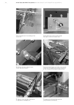
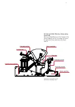
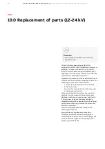
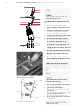
1. Switch with A-mechanism. On delivery the
draw bars (1.1) are detached,
a) test by hand that each arcing knife (1.2)
moves freely in the arc chamber (1.3),
b) pull the main contacts by hand (1.4) to
open position, see Fig.105. Attach the draw
bars to the main shaft (1.5) by the eccentric
bolt (1.6), and secure with washer and circlip.
2. Switch with K-mechanism. On delivery the
draw bars are connected.
3. Before operating the switch, check that the
surfaces of the main contacts are covered by
contact grease in the contact area. The
grease type Isoflex Topas NCA 52 must be
used if additional grease is required.
4. Operate the switch several times.
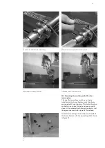
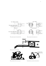
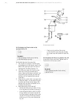
5. Check the main contact position at closed
switch- disconnector.
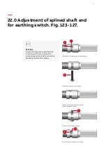
6. After all adjustments this position must be in
accordance with adjusting specification
shown on Fig. 106- in case of fixed contact
with a height of approximately 38 mm, main
contact in closed position should be between
two extreme positions: 2 mm above and 4
mm below the fixed contact. In case of fixed
contact with a height of approximately 46
mm, main contact in closed position should
not be below the fixed contact more than 10
mm while not extending below the lower
edge of the fixed contact. If this position is
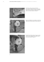
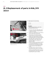
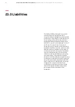
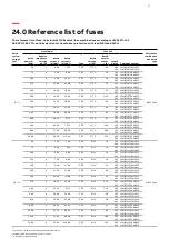
different then it must be adjusted by the
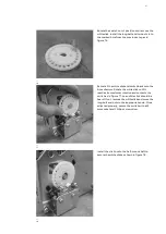
eccentric bolt (see Fig.110). To do this,
change positions of eccentric bolts placed on
the shaft arms (unscrew the M10 nut by
wrench first to make possible rotation of
eccentric bolt, rotate the eccentric bolt by
second flat wrench, then tighten the nut with
32 [Nm] +/-10% torque) to achieve proper
position of main knives.

