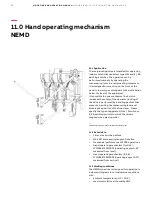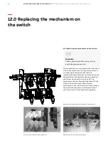
25
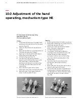
Opening
1. Make sure that all station doors are closed.
2. Remove the padlock securing manual drive of
switch-disconnector (if used),
3. Apply lever on the knurled shaft of manual
drive of the switch-disconnector,
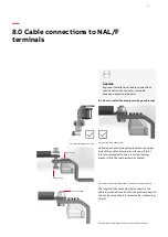
4. Pull the locking ring S (Fig.17).
5. Turn the lever in the opening direction -
according to the information shown on the
information label of manual drive of the
switch-disconnector; rotation should be
performed until the end - until the locking
ring snaps into the locked position of manual
drive. In result of this operation the spring of
the mechanism will be charged (Fig. 24). The
switch opens before - after rotating the lever
(about 20 degrees).
6. Check whether all poles of the switch-
disconnector have opened correctly (Fig.
105),
7. Remove the lever from the manual drive and
secure it with a padlock (if used),
8. If the switch-disconnector is equipped with
earthing switch, closing of earthing switch
can take place only after confirming that the
switch-disconnector is open (Fig.105).
For step-by-step instructions for installation of
the switch-disconnector with the HE hand
operation mechanism, see item ” Mounting the
hand operating mechanism type HE” .
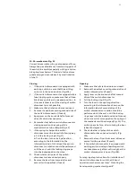
10.3 A-mechanism. Fig. 33
Current knives rotate with great speed and force.
Always keep a safe distance from moving parts of
the switch. Be careful especially with type A (dou-
ble spring) mechanism. This kind of drive stores
great energy and can release it by small rotation
of shaft.
Closing
1. If the switch-disconnector is equipped with
earthing switch, be sure that the earthing
switch is in the open position (Fig.105),
2. If the switch-disconnector is equipped with a
fuse tripping system, make sure that all fuse-
links have no strikers in released position - in
this case (striker is out) the closing of switch
disconnector is not possible,
3. Make sure that all station doors are closed.
4. Remove the padlock securing manual drive of
the switch-disconnector (if used),
5. Apply lever on the knurled shaft of manual
drive of switch-disconnector,
6. Remember that before switch-disconnector
closing operation, the spring of the
mechanism has to be charged (Fig.24)
7. If the spring is charged the switch-
disconnector can be closed in following way:
a. Pull the locking ring S (Fig.17)
b. Turn the lever in the closing direction -
according to the information on the
information label of HE drive of the switch-
disconnector; rotation should be performed
until the end - until the locking ring snaps
into the locked position the drive.
8. Check whether all poles of the switch-
disconnector have closed properly.
9. Remove the lever from manual drive and
secure it with a padlock (if used).

