54
MOU NTI NG A N D OPE R ATI ON M A N UA L
I N D O O R A I R S W I TC H - D I S CO N N EC TO R , N A L /N A L F/ V R
The switch-disconnector type NAL/VR is
equipped with DMC (BMC) (glassfibre-reinforced
polyester) or epoxy insulators. In case of DMC
(BMC) insulators all mounting is realized by self-
tapping screws. The epoxy insulators are fixed by
metric screws. DMC (BMC) insulator‘s
replacement procedure: if the same insulator and
screws are to be used after exchange of parts, the
following procedure must be followed:
•
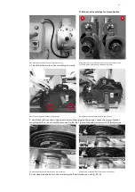
unscrew the self-tapping screws carefully,
•
brush them clean,
•
blow out the small particles in the threaded
hole (use eye protection).
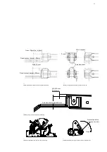
When mounting, the screws must be inserted
carefully into the threads in the insulator and
tightened with care. correct torque, see Fig. 114.
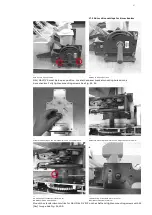
If using a new insulator, the holes should be
threaded to about 10 m deep by the self- tapping
screw before mounting. Remove the screw and
blow the holes clean.
The mounting takes place according to the
following procedures.
Epoxy insulator‘s replacement procedure:
The epoxy insulators can be unscrewed and
screwed again several times. In 24 kV design, the
screws should be tighten with special glue for
thread, eg LOCTITE 2701.
—
19.0 Replacement of parts (12-24 kV)
_
WARNING!
These operations shall be carried out by
specialists only!

