32
MOU NTI NG A N D OPE R ATI ON M A N UA L
I N D O O R A I R S W I TC H - D I S CO N N EC TO R , N A L /N A L F/ V R
—
14.0 Mounting of earthing switch
type E
14.1 Mounting of earthing switch type E/EB
(Fig.47)
The switch will normally be delivered for
connection of the hand operating mechanism on
the right hand side and any mechanical interlock
on the left side. The splined extension intended
for connection to the hand operating mechanism
will have free travel. The extension for the
interlock will be bolted to the shaft, see Fig.47.
14.2 Mounting the earthing switch to the switch-
disconnector type NAL/VR
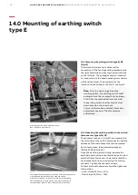
The contacts (see pos. 1, Fig.47) are mounted on
the terminals of the switch-disconnector, and the
surfaces of the main contacts are then covered
by contact grease. (Recommended grease:
ISOFLEX TOPAS NCA 52).
Close the earthing switch slowly (operate the
earthing switch using a handle placed on knurled
end shaft installed on short hole) and adjust the
fixed contacts to line up correctly with moving
contacts. Tighten the contacts screws.
Contact knife with draw bar should be tightened
in two steps:
- initial torque 32 Nm +/-10%,
- final torque 40 Nm +/- 10%.
—
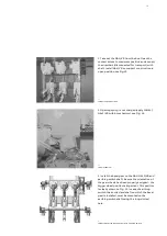
47 Earthing switch type E mounted on the
NAL/ VR switch-disconnector
—
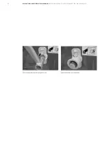
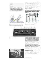
47a Tighten the earthing link to the frame of switch-disconnector
with torque 40 Nm. Between link’s head and switch-
disconnector frame must be only toothed washer (excluding
frames dedicated to Czech market, where toothed washer is
not applicable). Rest of washers must by above link’s head
_
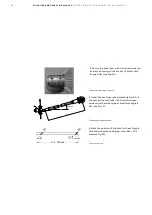
Note:
From the operating side of the
earthing switch, the earthing switch shaft
extension must be mounted on the oblong
hole. From the mechanical interlock side,
the earthing switch shaft extension must
be mounted on the round hole.
For more information and shaft extension
adjustment see point “Shaft extension
adjustment”.
1
2


