60
MOU NTI NG A N D OPE R ATI ON M A N UA L
I N D O O R A I R S W I TC H - D I S CO N N EC TO R , N A L /N A L F/ V R
1 / 1
1:5
A3
Sheet No.
Format
Language
Scale
Subtitle
Type
Derived from
Name
Date
Location
Revision
Drawn
Checked
Approved
EC No.
EN
Drawing status
Title
Drawing No.
Responsible
ABB Switzerland Ltd
Weight
Material
f
m
c
v
H
L
K
PROPRIETARY AND SECRET INFORMATION The information contained in this document has to be kept stric
tly confidential.
Any unauthorized use, reproduction, distribution or disclosure
to third parties
is strictly forbidden. ABB reserves all rights regarding Intell
ectual Property Rights.
Thread Quality Tolerance
"6g-6H" ISO 965
ISO 2768 T.1 Lengths and Angle
ISO 2768 T.2 Geometrical Tolerances
Surface
Surface code
Coord. punching N.C.Mach.
and unfold JS11
Standard Tolerances for Machining and Forming
© Copyright
ABB. All rights reserved.
2016
5
4
3
2
1
H
G
F
D
C
B
A
H
G
F
E
C
B
A
5
4
3
2
1
Group Technology Management
M. Mańkowski
PL-PSY
05.03.2020
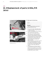
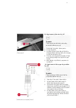
21.5 Replacement of the piston with piston rod.
Fig. 121
1. Remove spring mechanism before starting (if
a mechanism is installed).
2. Close the switch-disconnector.
3. Disconnect the lower part of draw bar from
the main shaft.
4. Disconnect the piston rod from the operating
shaft and piston can be taken out.
5. New piston is installed the reverse way.
6. Connect the drawbar to the eccentric bolt on
the main shaft."
—
121 Replacement of the piston with piston rod.
—
122 Tightening torque for screws NAL/VR 36-40,5
_
WARNING!
These operations shall be carried out by
authorised ABB service only!
_
Note:
Piston and cylinder MUST NOT be
greased or lubricated.
_
Note:
A certain degree of adjustment can
be made by moving the hollow insulator.
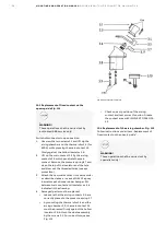
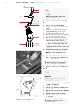
21.4 Replacement of the hollow insulator. Fig.
120
1. Disconnect the switch-disconnector.
2. The spring mechanism is removed from the
frame.
3. All draw bars are detached from the crank
arm of the operating shaft, see Fig.116.
4. Turn the operating shaft to one side.
5. Disconnect the piston rod from the operating
shaft and piston can be taken out.
6. Undo the mounting screws on insulator.
7. The hollow insulator is attached to the frame
by 4 screws M10 (spanner-gap 17). New
insulator is mounted. If contact blocks and
arc extinguishing chambers are to be used
again, these must be mounted to the
insulator BEFORE the insulator is fitted to the
switch frame.
8. Add spring mechanism and connect all draw
bars to the crank arms as described in
paragraph “Hollow insulator with arcing
chamber”.
9. The position of the insulator is checked and
adjusted as described in paragraph “Hollow
insulator with arcing chamber”.
—
120 Replacement of the hollow insulator.
_
WARNING!
These operations shall be carried out by
authorised ABB service only!
15 Nm
11
9
1
2
3
8
6
4
10
7
5
40 Nm
12


