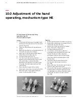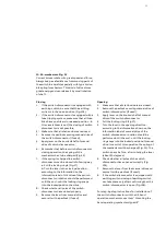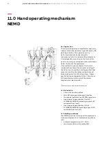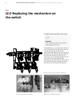
30
MOU NTI NG A N D OPE R ATI ON M A N UA L
I N D O O R A I R S W I TC H - D I S CO N N EC TO R , N A L /N A L F/ V R
—
13.0 Mounting of fuse-base
13.1 Mounting of fuse-base
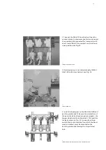
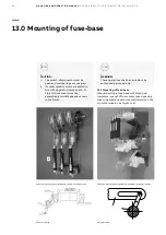
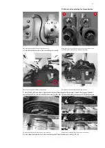
When mounting a fuse-base with three post
insulators, one set of fuse contacts and possibly
fuse trip accessories are mounted directly on the
switch terminals, see Fig. 41 or 42.
3–6 mm
15 14 13
7
5 6 7
12
11
1
11
9
8
1 2 3 4
MEC.
10
max. e÷8 mm
e (DIN 43625)
—
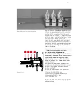
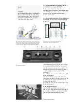
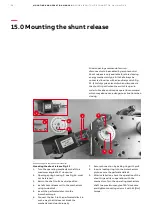
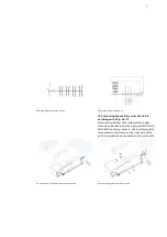
41 Switch-disconnector type NALF mounted on the pivot side
—
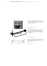
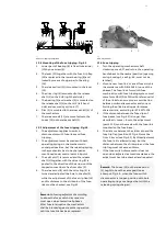
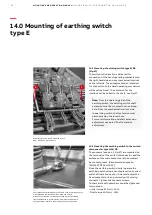
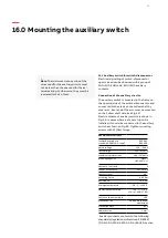
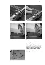
43 Fuse tripping
—
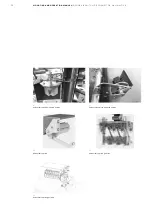
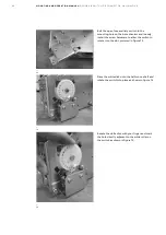
44 Tripping rod
—
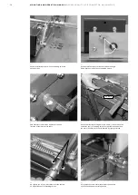
42 Switch-disconnector type NALF mounted on the oppening side
_
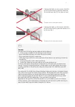
CAUTION!
1. The switch-disconnector must be
open and main springs not charged.
2. If contact plastic covers are added to
box with apparatus (component „A”
Fig.41), these covers must be
assembled at middle phase as shown
in the Fig.41.
_
WARNING!
These operations shall be carried out by
authorised personnel only!


