5
058
21.0 Replacement of parts in
NAL/VR 36 kV
058
21.1 Replacement of contact
knives
059
21.2 Replacement of draw bar.
Fig. 116
059
21.3 Replacement of the
supporting insulator. Fig. 118
060
21.4 Replacement of the
hollow insulator. Fig. 119
060
21.5 Replacement of the
piston with piston rod.
Fig. 120
061
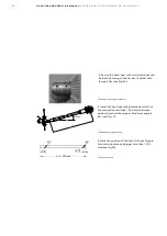
22.0 Adjustment of splined
shaft end for earthing switch.
Fig. 122- 126
062
23.0 Liabilities
063
24.0 Reference list of fuses
068
25.0 Environmental
declaration
068
25.1 Environmental
Certification Life expectancy
of product
068
25.2 End-of-life
045
17.2 Motor drive settings for
A-mechanism
047
17.3 Motor drive settings for
K-mechanism
048
17.4 UEMC 41
049
18.0 Service and maintenance
049
18.1 Cleaning
049
18.2 Switch-disconnector in
service
050
18.3 Mechanical overhaul
050
18.4 Electrical overhaul in
service
050
18.5 Control of NAL/VR knives
after mounting. Fig. 105-106
054
19.0 Replacement of parts
(12-24 kV)
055
19.1 Replacement of contact
knife with draw bar. Fig.110
055
19.2 Pivot side support
insulator. Fig. 110
056
19.3 Replacement of fixed
contact on the opening side
Fig. 111
056
19.4 Replacement of the
arcing chamber. Fig. 111
057
20.0 Replacement of
insulators
057
20.1 Hollow insulators with
arcing chamber. Fig. 113
057
20.2 Insulator for fuse-base
and quick make earthing
switch

