


Planning the electrical installation 45
Selecting the power cables
General rules
Dimension the supply (input power) and motor cables
according to local
regulations
.
• The cable must be able to carry the drive load current. See the chapter
for the rated currents.
• The cable must be rated for at least 70
°
C maximum permissible temperature of
conductor in continuous use. For UL installations use 75 °C copper wiring only.
• The conductivity of the PE conductor must be equal to that of a phase conductor
(i.e. same cross-sectional area).
• 600 VAC cable is accepted for up to 500 VAC.
• Refer to the chapter
for EMC requirements.
Symmetrical shielded motor cable must be used (see the figure below) to meet the
EMC requirements of the CE mark.
A four-conductor system is allowed for input cabling, but shielded symmetrical cable
is recommended. Compared to a four-conductor system, the use of symmetrical
shielded cable reduces electromagnetic emission of the whole drive system as well
as motor bearing currents and wear.
The motor cable and its PE pigtail (twisted shield) must be kept as short as possible
in order to reduce electromagnetic emission.
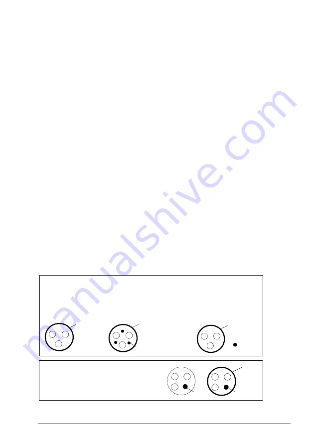
Alternative power cable types
Power cable types that can be used with the drive are represented below.
Symmetrical shielded cable: three phase conductors
and a concentric or otherwise symmetrically
constructed PE conductor, and a shield
Motor cable
(also recommended for supply cabling)
PE conductor
and shield
Shield
Shield
Note:
A separate PE conductor is
required if the conductivity of the
cable shield is not sufficient for the
purpose.
A four-conductor system: three phase conductors
and a protective conductor.
Shield
PE
PE
Allowed for supply cabling
PE
PE
Summary of Contents for MicroFlex e190
Page 1: ...ABB motion control User s manual MicroFlex e190 servo drive ...
Page 4: ......
Page 12: ...12 Table of contents ...
Page 26: ...26 Introduction to the manual ...
Page 90: ...90 Electrical installation input output ...
Page 146: ...146 Maintenance ...
Page 178: ...178 Resistor braking ...
Page 186: ...186 Accessories ...
Page 208: ...208 Appendix Safe Torque Off STO ...