5.
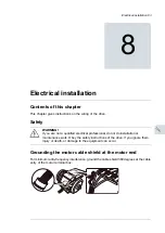
Remove rubber grommets from the entry plate for the cables to be connected. Cut
adequate holes into the rubber grommets. Slide the grommets onto the cables. Slide
the cables through the entry plate and attach the grommets to the holes.
6.
Attach the conductive sleeves to the cable shields with cable ties. Tie up the unused
conductive sleeves with cable ties. An example of bottom entry is shown below. For top
entry, place the grommet upwards.
■
Power cable connection procedure
Stop the drive and do the steps in section
Electrical safety precautions (page 15)
before
you start the work.
1.
Connect the cable shields of the motor cables and any separate ground conductors or
cables to the ground terminal of the drive module or to the cabinet ground bar.
2.
Connect the phase conductors of the motor cables to terminals T1/U2, T2/V2 and T3/W2
of the drive module. For the tightening torques, see the technical data.
3.
Drive modules with D150: Connect the brake resistor conductors to the R+ and
R- terminals. For the tightening torques, see the technical data.
96 Electrical installation
Summary of Contents for ACS880-04FXT
Page 1: ... ABB INDUSTRIAL DRIVES ACS880 04FXT drive module packages Hardware manual ...
Page 2: ......
Page 4: ......
Page 40: ...40 ...
Page 54: ...54 ...
Page 82: ...82 ...
Page 86: ...M10 86 Electrical installation ...
Page 106: ...106 ...
Page 118: ...118 ...
Page 122: ...122 ...
Page 132: ...132 ...
Page 136: ...136 ...
Page 158: ...158 ...
Page 160: ...Standard configuration IP00 UL Type Open 160 Dimension drawings ...
Page 161: ...Drive module with optional support brackets IP00 UL Type Open Dimension drawings 161 ...
Page 163: ...Mounting plate opening 3AXD50000038119 Dimension drawings 163 ...
Page 164: ...3AXD50000038119 164 Dimension drawings ...
Page 182: ... Declaration of conformity 182 The Safe torque off function ...
Page 183: ...The Safe torque off function 183 ...
Page 184: ...184 ...


