


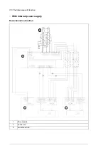


Wiring
For the electrical specifications of the STO connection, see the
BCU-02/12/22 control units
hardware manual
(3AUA0000113605 [English]).
■
Activation switch
In the wiring diagrams, the activation switch has the designation [K]. This represents a
component such as a manually operated switch, an emergency stop push button switch, or
the contacts of a safety relay or safety PLC.
•
In case a manually operated activation switch is used, the switch must be of a type that
can be locked out to the open position.
•
The contacts of the switch or relay must open/close within 200 ms of each other.
•
An FSO-xx safety functions module or an FPTC-0x thermistor protection module can
also be used. For more information, see the module documentation.
■
Cable types and lengths
•
Double-shielded twisted-pair cable is recommended.
•
Maximum cable lengths:
•
300 m (1000 ft) between activation switch [K] and drive control unit
•
60 m (200 ft) between multiple drives or inverter units
•
60 m (200 ft) between external power supply and first control unit
Note:
A short-circuit in the wiring between the switch and an STO terminal causes a
dangerous fault. Therefore, it is recommended to use a safety relay (including wiring
diagnostics) or a wiring method (shield grounding, channel separation) which reduces or
eliminates the risk caused by the short-circuit.
Note:
The voltage at the STO input terminals of the control unit must be at least 17 V DC
to be interpreted as “1”.
The pulse tolerance of the input channels is 1 ms.
■
Grounding of protective shields
•
Ground the shield in the cabling between the activation switch and the control unit at
the control unit only.
•
Ground the shield in the cabling between two control units at one control unit only.
The Safe torque off function 169
Summary of Contents for ACS880-04FXT
Page 1: ... ABB INDUSTRIAL DRIVES ACS880 04FXT drive module packages Hardware manual ...
Page 2: ......
Page 4: ......
Page 40: ...40 ...
Page 54: ...54 ...
Page 82: ...82 ...
Page 86: ...M10 86 Electrical installation ...
Page 106: ...106 ...
Page 118: ...118 ...
Page 122: ...122 ...
Page 132: ...132 ...
Page 136: ...136 ...
Page 158: ...158 ...
Page 160: ...Standard configuration IP00 UL Type Open 160 Dimension drawings ...
Page 161: ...Drive module with optional support brackets IP00 UL Type Open Dimension drawings 161 ...
Page 163: ...Mounting plate opening 3AXD50000038119 Dimension drawings 163 ...
Page 164: ...3AXD50000038119 164 Dimension drawings ...
Page 182: ... Declaration of conformity 182 The Safe torque off function ...
Page 183: ...The Safe torque off function 183 ...
Page 184: ...184 ...


