Overview of power and control connections
The diagram below shows the power connections and control interfaces of the drive unit.
BCU
BPOW
X3
XS
TO
O
U
T
5
6
7
8
T1/U2
T2/V2
T3/W2
R-
R+
t°
UDC-
L1/U1
L2/V1
L3/W1
L1
L2
L3
PE
PE
UDC+
BGDR
X7
X8
M
3 ~
T1/U2
T2/V2
T3/W2
R-
R+
t°
UDC-
L1/U1
L2/V1
L3/W1
L1
L2
PE
PE
UDC+
BPOW
X3 1 2
BGDR
X7
1
2
SO
IA
X8
1
2
ZI
N
T
V10 V20
V1 V2
2
1
2
1
2
SO
IA
ZI
N
T
V10 V20
V1 V2
1 2
FXX
FXX
FXXX
CLOSE
XPOW
1
2
V1T
V1R
V2T
V2R
L3
ACS880-04F-xxxx-x+P943
ACS880-04F-
xxxx-x+P943
FSO
1
2
3
5
4
6
7
8
9
11
12
10
11
12
13
14
Analog and digital I/O extension modules, feedback interface modules and fieldbus communication
modules can be inserted into slots 1, 2 and 3. See section
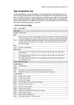
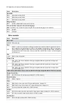
Type designation key (page 37)
1,2,3
Slot 4 for RDCO-0x
4
Connector X12 for the FSO-xx safety functions module
5
Memory unit connection
6
32 Operation principle and hardware description
Summary of Contents for ACS880-04FXT
Page 1: ... ABB INDUSTRIAL DRIVES ACS880 04FXT drive module packages Hardware manual ...
Page 2: ......
Page 4: ......
Page 40: ...40 ...
Page 54: ...54 ...
Page 82: ...82 ...
Page 86: ...M10 86 Electrical installation ...
Page 106: ...106 ...
Page 118: ...118 ...
Page 122: ...122 ...
Page 132: ...132 ...
Page 136: ...136 ...
Page 158: ...158 ...
Page 160: ...Standard configuration IP00 UL Type Open 160 Dimension drawings ...
Page 161: ...Drive module with optional support brackets IP00 UL Type Open Dimension drawings 161 ...
Page 163: ...Mounting plate opening 3AXD50000038119 Dimension drawings 163 ...
Page 164: ...3AXD50000038119 164 Dimension drawings ...
Page 182: ... Declaration of conformity 182 The Safe torque off function ...
Page 183: ...The Safe torque off function 183 ...
Page 184: ...184 ...


