background image

Markings

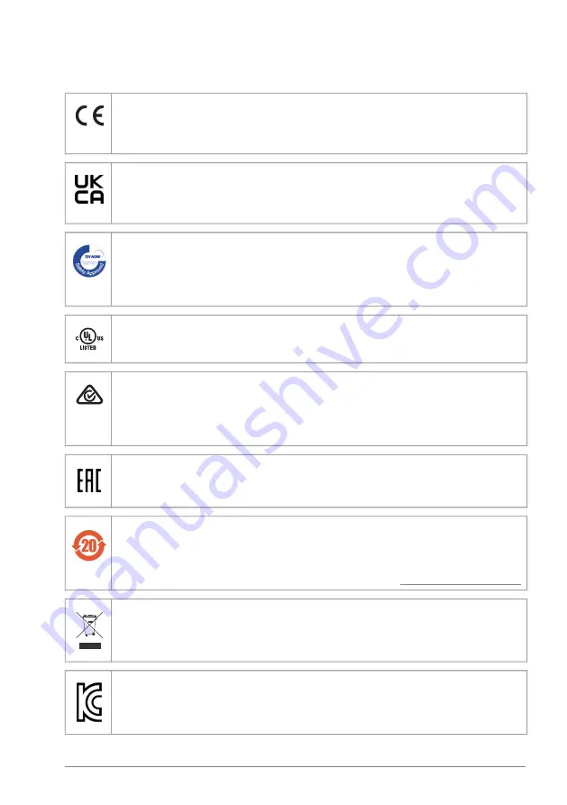
CE mark
Product complies with the applicable European Union legislation. For fulfilling
the EMC requirements, see the additional information concerning the drive EMC
compliance (IEC/EN 61800-3).

UKCA (UK Conformity Assessed) mark
Product complies with the applicable United Kingdom’s legislation (Statutory In-
struments). Marking is required for products being placed on the market in Great
Britain (England, Wales and Scotland).

TÜV Safety Approved mark (functional safety)
Product contains Safe torque off and possibly other (optional) safety functions
which are certified by TÜV according to the relevant functional safety standards.
Applicable to drives and inverters; not applicable to supply, brake or DC/DC con-
verter units or modules.

UL Listed mark for USA and Canada
Product has been tested and evaluated against the relevant North American
standards by the Underwriters Laboratories. Valid with rated voltages up to 600 V.

RCM mark
Product complies with Australian and New Zealand requirements specific to EMC,
telecommunications and electrical safety. For fulfilling the EMC requirements,
see the additional information concerning the drive EMC compliance
(IEC/EN 61800-3).

EAC (Eurasian Conformity) mark
Product complies with the technical regulations of the Eurasian Customs Union.
EAC mark is required in Russia, Belarus and Kazakhstan.

Electronic Information Products (EIP) symbol including an Environment Friendly
Use Period (EFUP).
Product is compliant with the People’s Republic of China Electronic Industry
Standard (SJ/T 11364-2014) about hazardous substances. The EFUP is 20 years.
China RoHS II Declaration of Conformity is available from

https://library.abb.com

.

WEEE mark
At the end of life the product should enter the recycling system at an appropriate
collection point and not placed in the normal waste stream.

KC mark
Product complies with Korean Registration of Broadcasting and Communications
Equipment Clause 3, Article 58-2 of Radio Waves Act.

Technical data 123

Summary of Contents for ACS180

Page 1: ...ABB MACHINERY DRIVES ACS180 drives Hardware manual...

Page 2: ......

Page 3: ...ACS180 drives Hardware manual Table of contents 1 Safety instructions 4 Mechanical installation 6 Electrical installation 3AXD50000467945 Rev B EN Original instructions EFFECTIVE 2022 06 28...

Page 4: ......

Page 5: ...start up maintenance 20 Safety in operation 2 Introduction to the manual 21 Contents of this chapter 21 Applicability 21 Target audience 21 Purpose of the manual 21 Categorization by frame size 21 Qu...

Page 6: ...the electrical installation 43 Contents of this chapter 43 Limitation of liability 43 Selecting the main supply disconnecting device 44 European Union and United Kingdom 44 North America 44 Other regi...

Page 7: ...e compatibility 56 Implementing the Emergency stop function 56 Implementing the Safe torque off function 56 Using a safety switch between the drive and the motor 56 Implementing the control of a conta...

Page 8: ...Description of symbols 80 Recommended maintenance intervals after start up 80 Cleaning the heatsink 81 Replacing the cooling fans 81 To replace the cooling fan for frame size R1 83 To replace the cool...

Page 9: ...unctionality and motor cable length 118 EMC compatibility and motor cable length 119 Control connection data 120 Brake resistor connection data 120 Energy efficiency data ecodesign 120 Degrees of prot...

Page 10: ...asuring the insulation 141 Connecting power cables 141 Connection the control cables 141 Start up 12 The Safe torque off function 143 Contents of this chapter 143 Description 144 Compliance with the E...

Page 11: ...ion test procedure 154 Use 156 Maintenance 156 Competence 157 Fault tracing 158 Safety data 160 Terms and abbreviations 161 T V certificate 162 Declarations of conformity Further information Table of...

Page 12: ...12...

Page 13: ...you how to prevent the danger Notes draw attention to a particular condition or fact or give information on a subject The manual uses these warning symbols WARNING Electricity warning tells about haz...

Page 14: ...there is sufficient cooling See the technical data Before you connect voltage to the drive make sure that all covers are in place Do not remove the covers when voltage is connected Before you adjust...

Page 15: ...t immediately after fault reset unless you configure the drive for pulse start See the firmware manual If the drive is in remote control mode you cannot stop or start the drive with the control panel...

Page 16: ...ect power from the drive always wait 5 minutes to let the intermediate circuit capacitors discharge before you continue 3 Protect any other energized parts in the work location against contact 4 Take...

Page 17: ...interfere with the function of such devices This can cause a health hazard Note When the drive is connected to the input power the motor cable terminals and the DC bus are at a dangerous voltage After...

Page 18: ...joining equipment This is necessary for the personnel safety Make sure that the conductivity of the protective earth PE conductors is sufficient and that other requirements are met See the electrical...

Page 19: ...can occur These functions reset the drive automatically and continue operation after a fault or supply break If these functions are activated the installation must be clearly marked as defined in IEC...

Page 20: ...y or through any mechanical connection like belt nip rope etc Do the steps in section Electrical safety precautions page 16 Install temporary grounding to the drive output terminals T1 U T2 V T3 W Con...

Page 21: ...ng electrical components and electrical schematic symbols The manual is written for readers worldwide Both SI and imperial units are shown Purpose of the manual This manual gives information needed to...

Page 22: ...be connected to an IT ungrounded system make sure that the internal EMC filter is not connected Installing the drive page 40 Install the drive mechanically Routing the cables page 50 Route the cables...

Page 23: ...DC circuit between rectifier and inverter Intermediate circuit Converts direct current and voltage to alternating current and voltage Inverter A pre defined set of default values of parameters in a dr...

Page 24: ...S W and ACH AP H W Assistant control panel user s manual Tool and maintenance manuals 3AUA0000094606 Drive Composer Start up and maintenance PC tool user s manual 3BFE64059629 Converter module capaci...

Page 25: ...nts of this chapter This chapter describes the operation principle layout type designation label and type designation information It shows a general diagram of the power connections and control interf...

Page 26: ...the intermediate DC circuit of the drive to the brake resistor when it is necessary and if an external brake resistor is connected to the drive The chopper operates when the DC link voltage exceeds a...

Page 27: ...ion motor 8 Control panel display and status LED 2 Fixed control terminals 9 Motor connection terminal 3 Front cover 10 Cooling fan 4 Model information label 11 Panel and PC tool port RJ45 5 Type desi...

Page 28: ...el display and status LED 2 Fixed control terminals 9 Motor connection terminal 3 Front cover 10 Cooling fan 4 Model information label 11 Panel and PC tool port RJ45 5 Cold configuration connection fo...

Page 29: ...connection 3 Modbus termination jumper 4 Communication mode jumper 5 Digital inputs and outputs 6 Analog inputs and outputs 7 EIA 485 Modbus RTU 8 Panel connector external panel or adapter for PC conn...

Page 30: ...tion jumper 3 Communication mode jumper 4 Digital inputs and outputs 5 Analog inputs and outputs 6 EIA 485 Modbus RTU 7 Panel connector external panel or adapter for PC connection 8 Cold configuration...

Page 31: ...you can order a control panel platform for cabinet door installation These panel platforms are available Description Type Control panel mounting platform flush mounting and cable DPMP 01 Control pane...

Page 32: ...from 0001 Type designation key The type designation shows the specifications and configuration of the drive The table below presents the type code digits Sample type code 1 ACS180 04N 02A6 4 Sample ty...

Page 33: ...et values 6 Stop button stop the dr 7 Back button open the O back in the menu 8 Options menu 9 Status light green and r state and potential probl 1 2 3 4 5 6 7 d e e c a b Display Home view 1 a Contro...

Page 34: ...for local control and Rem for remote control The status icons The reference target value From the Home view push the Back key to open the Options view and push the OK key to open the Menu Adjust the...

Page 35: ...he reference View the active fault View a list of the active warnings Menu To open the Menu push the OK key in the Home view To navigate in the Menu push the up and down arrow keys to move between men...

Page 36: ...36...

Page 37: ...irements Make sure that there is a minimum of 75 mm of free space at the top and bottom of the drive at the cooling air inlet and outlet You can install several drives side by side If you install fram...

Page 38: ...ertical as possible and strong enough to support the drive There is sufficient free space around the drive for cooling maintenance and operation See the free space specifications for the drive Make su...

Page 39: ...Package contents 1 2 3 1 drive 2 installation accessories cable clamps metal grounding plate screws etc 3 quick installation and start up guide Mechanical installation 39...

Page 40: ...oles See the diagram below and Dimensions and weights page 108 2 Make the holes for the mounting screws and fasten the screws Use plugs or anchors if needed See section Dimensions and weights page 108...

Page 41: ...4 Tighten the mounting screws Mechanical installation 41...

Page 42: ...ush and hold the locking button down 3 Put the top tabs of the drive onto the top edge of the DIN installation rail 4 Put the drive against the bottom edge of the DIN installation rail 5 Release the l...

Page 43: ...oever for any installation which breaches the local laws and or other regulations Furthermore if the recommendations given by ABB are not followed the drive may experience problems that the warranty d...

Page 44: ...cting device must conform to the applicable local safety regulations Selecting the main contactor You can equip the drive with a main contactor Follow these guidelines when you select a main contactor...

Page 45: ...for up to 500 V AC 750 V AC cable is accepted for up to 600 V AC 1000 V AC cable is accepted for up to 690 V AC To comply with the EMC requirements of the CE mark use one of the preferred cable types...

Page 46: ...types Use as motor cabling and as brake resistor cabling Use as input power cabling Cable type Yes with phase conductor smaller than 10 mm2 8 AWG Cu or motors up to 30 kW 40 hp Yes with phase conduct...

Page 47: ...d on the shield inductance which must be low and only slightly dependent on frequency The requirements are easily met with a copper or aluminum shield armor The cross section of a steel shield must be...

Page 48: ...l ground path provided this path is a solid path capable of handling ground currents 2 See NFPA NEC 70 UL and local codes for your application 3 Non metallic conduit use underground is allowed however...

Page 49: ...y use shielded control cables Use a double shielded twisted pair cable for analog signals This type of cable is recommended for the pulse encoder signals also Use one individually shielded pair for ea...

Page 50: ...es General guidelines IEC Route the motor cable away from other cables Motor cables of several drives can be run in parallel installed next to each other Install the motor cable input power cable and...

Page 51: ...uidelines North America Make sure that the installation is in accordance with national and local codes Obey these general guidelines Use separate conduits for the input power motor brake resistor opti...

Page 52: ...uipment are installed on the motor cable between the drive and the motor Install the equipment in a metal enclosure Use either a symmetrical shielded cable or install the cabling in a metal conduit Ma...

Page 53: ...joining equipment in case of a short circuit inside the drive When located at the distribution board the fuses also protect the input power cable against short circuits See the drive technical data fo...

Page 54: ...temperature indication given by motor temperature sensors The motor thermal protection model supports thermal memory retention and speed sensitivity The user can tune the thermal model further by fee...

Page 55: ...nd insulated with basic insulation from other low voltage circuits The insulation must be rated for the same voltage level as the drive main circuit Note Extra low voltage circuits for example 24 V DC...

Page 56: ...he Safe torque off function page 143 Using a safety switch between the drive and the motor ABB recommends to install a safety switch between the permanent magnet motor and the drive output The switch...

Page 57: ...r control mode Protecting the contacts of relay outputs Inductive loads relays contactors motors cause voltage transients when switched off Install the protective component as close to the inductive l...

Page 58: ...58...

Page 59: ...ol cables install optional modules connect a PC Warnings WARNING Obey the safety instructions of the drive If you ignore them injury or death or damage to the equipment can occur If you are not a qual...

Page 60: ...ble Before you connect the input power cable to the drive measure its insulation resistance according to local regulations Measuring the insulation resistance of the motor and motor cable WARNING Obey...

Page 61: ...another system you must disconnect the EMC filter Note If you disconnect the EMC filter the electromagnetic compatibility of the drive decreases WARNING Do not install a drive with the internal EMC f...

Page 62: ...ded wye A Remove Remove Do not remove Metal EMC Do not remove Do not remove Do not remove1 Plastic Remove Do not remove Do not remove Metal VAR Do not remove Do not remove Do not remove Plastic A B1 B...

Page 63: ...e EMC performance because the internal EMC filter is disconnected ABB does not guarantee the functioning of the ground leakage detector built inside the drive In large systems the residual current dev...

Page 64: ...or each grounding system Electrical power system type UL3 G UL2 G UL1 G UL L Symmetrically grounded TN system TN S system 0 58 X 0 58 X 0 58 X X Corner grounded delta system nonsym metrical 0 1 0 X 1...

Page 65: ...rounding cable or a cable with a separate PE conductor for the line side if the conductivity of the fourth conductor or shield does not meet the requirements for the PE conductor 5 Motor cable Note AB...

Page 66: ...can occur If you are not a qualified electrical professional do not do installation commissioning or maintenance work 1 Stop the drive and do the steps in section Electrical safety precautions page 1...

Page 67: ...it to the grounding terminal 6 Connect the phase conductors of the motor cable to the T1 U T2 V and T3 W motor terminals 7 For frame sizes R2 R4 if you use a brake resistor connect the brake resistor...

Page 68: ...s required by the drive safety standards IEC61800 5 and UL 61800 5 11 Connect the phase conductors of the input power cable to the L1 L2 and L3 input terminals 12 Mechanically attach the cables on the...

Page 69: ...iary voltage DO SRC Analog I O Speed reference 0 10V AI1 DI5 Analog input circuit common AGND Not used AI2 Analog output circuit common AGND Output frequency 0 20mA AO Ref voltage 10 V DC 10V Signal c...

Page 70: ...If you ignore them injury or death or damage to the equipment can occur If you are not a qualified electrical professional do not do installation commissioning or maintenance work 1 Stop the drive an...

Page 71: ...ding clamp to connect the cable to the grounding tab 6 Strip the ends of the control cable conductors For stranded multi wire conductors install ferrules at the bare conductor ends 7 Connect the condu...

Page 72: ...han 200 pF per meter 60 pF per foot Foil or braided shields are acceptable The connection diagram is shown below With signal ground reference terminal G R 1 B A AGND Shield J1 J2 4 B A AGND Shield J1...

Page 73: ...wer supply 0 V DC 24 V DC DI1 DI2 DI3 DI4 24 V DGND DCOM DI1 DI2 DI3 DI4 24 V DGND DCOM NPN configuration for digital inputs Internal and external 24 V power supply connections for NPN sink configurat...

Page 74: ...ss actual value measurement or reference 0 4 20 mA Rin 205 ohm AI2 AGND Auxiliary voltage output non isolated 24 V DC max 100 mA 24V DGND Safe torque off For the drive to start both STO connections mu...

Page 75: ...gth of the cable is 3 m 9 8 ft Use a USB to RJ45 converter You can order it from ABB BCBL 01 3AXD50000032449 Connect the cable to the Panel and PC tool port RJ45 For information on the Drive composer...

Page 76: ...76...

Page 77: ...you ignore them injury or death or damage to the equipment can occur If you are not a qualified electrical professional do not do installation commissioning or maintenance work WARNING Stop the drive...

Page 78: ...tective earth ground conductor between the motor and the drive The conductor is connected to the correct terminal and the terminal is tightened to the correct torque Grounding has also been measured a...

Page 79: ...nce schedule is available on the Internet https new abb com drives services maintenance preventive maintenance For more information consult your local ABB Service representative www abb com searchchan...

Page 80: ...rated within the specified ratings and ambient conditions ABB recommends annual drive inspections to ensure the highest reliability and optimum performance Long term operation near the specified maxim...

Page 81: ...ing the cooling fans These instructions are applicable only to frame sizes R1 R2 R3 and R4 Frame R0 units do not have a cooling fan Parameter 05 04 Fan on time counter shows the running time of the co...

Page 82: ...ps and remove the fan from the fan cover 6 Install the new fan into the fan cover Make sure that the air flow is in the correct direction The air flows in from the bottom of the drive and out from the...

Page 83: ...rrectly Push the cover to lock into position 8 To replace the cooling fan for frame size R2 WARNING Obey the safety instructions of the drive If you ignore them injury or death or damage to the equipm...

Page 84: ...lift the fan cover out of the drive Note that the fan cover holds the cooling fan 3 2 2 4 Disconnect the fan power cable 4 5 Free the fan clips and remove the fan from the fan cover 6 Install the new...

Page 85: ...o replace the cooling fan for frame size R3 WARNING Obey the safety instructions of the drive If you ignore them injury or death or damage to the equipment can occur If you are not a qualified electri...

Page 86: ...2 3 Carefully lift the fan cover out of the drive The fan cover holds the cooling fan 3 4 Disconnect the fan power cable 4 86 Maintenance...

Page 87: ...ection The air flows in from the bottom of the drive and out from the top of the drive 5 6 Connect the fan power cable 6 7 Carefully put the fan cover into position in the drive Make sure that the fan...

Page 88: ...professional do not do installation commissioning or maintenance work 1 Stop the drive and do the steps in section Electrical safety precautions page 16 before you start the work 2 Use a suitable flat...

Page 89: ...effect on the life of the capacitors Capacitor life can be extended by decreasing the surrounding air temperature Capacitor failure is usually followed by damage to the unit and an input cable fuse fa...

Page 90: ...90...

Page 91: ...inal use Max current PHd IHd PLd ILd Pn In Imax I1 I1 kW A kW A kW A A A A 1 phase Un 200 240 V R0 0 25 1 8 0 37 2 3 0 37 2 4 3 2 3 3 5 02A4 1 R0 0 37 2 4 0 55 3 5 0 55 3 7 4 3 4 8 6 9 03A7 1 R0 0 55...

Page 92: ...55 1 8 2 2 1 5 2 8 01A8 4 R0 0 55 1 8 0 75 2 5 0 75 2 6 3 2 1 9 3 6 02A6 4 R0 0 75 2 4 1 1 3 1 1 1 3 3 4 3 2 5 4 6 03A3 4 R1 1 1 3 3 1 5 3 8 1 5 4 5 9 3 3 6 3 04A0 4 R1 1 5 4 2 2 5 3 2 2 5 6 7 2 4 6...

Page 93: ...3 9 8 14 7 09A8 2 R2 3 10 7 3 14 6 19 3 15 6 19 2 15A6 2 R2 3 12 2 5 16 7 22 17 5 23 6 17A5 2 R3 5 17 5 7 5 24 2 31 5 25 27 2 25A0 2 R3 7 5 25 10 30 8 45 32 35 033A 2 R4 10 32 15 46 2 57 6 48 48 048A...

Page 94: ...Maximum output current with 110 overload allowed for one minute every ten minutes PLd Typical motor power in light duty use 110 overload IHd Maximum output current with 150 overload allowed for one m...

Page 95: ...f 17A0 4 drive s nominal output current at 55 C surrounding air temperature is 0 775 Multiply the nominal drive output current by all the applicable derating factors In this example the derated output...

Page 96: ...sufficient because it is higher than the required current Example 2 UL NEC How to calculate the required drive The application requires a maximum of 12 0 A of motor current with a 10 overload for one...

Page 97: ...80 100 10 0 10 20 30 40 50 60 Derating factor Ambient temperature C F 140 122 104 86 68 50 32 14 0 25 50 75 100 Derating factor 10 0 10 20 30 40 50 60 Ambient temperature C F 140 122 104 86 68 50 32 1...

Page 98: ...Derating factor 90 Ambient temperature C F 158 140 122 104 86 68 50 32 14 Derating factor for IN and ILd on ACS180 1 2 0 20 40 60 80 100 10 0 10 20 30 40 50 60 70 Derating factor Ambient temperature 7...

Page 99: ...on ACS180 04x 055A 2 038A 4 050A 4 Altitude derating 1000 2000 m above sea level the derating is 1 for every 100 m 330 ft To calculate the output current multiply the current in the rating table with...

Page 100: ...A6 2 0 7 0 8 1 1 17A5 2 0 5 0 7 1 1 25A0 2 0 5 0 7 1 1 033A 2 0 5 0 7 1 1 048A 2 0 5 0 7 1 1 055A 2 3 phase Un 380 480 V 0 4 0 6 1 1 01A8 4 0 4 0 6 1 1 02A6 4 0 4 0 6 1 1 03A3 4 0 4 0 6 1 1 04A0 4 0 4...

Page 101: ...cur rent Input current ACS180 04 V A2s A A A 1 phase Un 200 240 V C10G10 500 310 10 62 5 02A4 1 C10G16 500 680 16 150 6 9 03A7 1 C10G16 500 680 16 193 9 04A8 1 C10G20 500 1200 20 275 12 6 06A9 1 C10G...

Page 102: ...ng I2t Nominal current Min short circuit cur rent Input current ACS180 04 V A2s A A A 1 phase Un 200 240 V FWP 32G14F 690 679 32 62 5 02A4 1 FWP 32G14F 690 679 32 150 6 9 03A7 1 FWP 40G14F 690 1331 40...

Page 103: ...FWP 125A 700 7300 125 640 49 038A 4 FWP 150A 700 11700 160 800 55 7 045A 4 FWP 150A 700 11700 160 800 55 7 050A 4 UL fuses UL NEC Type Buss mann type Voltage rating Nominal current Min short cir cuit...

Page 104: ...JJS 40 600 40 400 31 8 25A0 4 UL class T JJS 60 600 60 504 40 9 033A 4 UL class T JJS 70 600 70 640 49 038A 4 UL class T JJS 70 600 70 800 55 7 045A 4 UL class T JJS 70 600 70 800 55 7 050A 4 Alterna...

Page 105: ...onments Miniature circuit breaker Frame ACS180 04 ABB type 1 phase Un 200 240 V S201P B10NA R0 02A4 1 S201P B10NA R0 03A7 1 S201P B16NA R0 04A8 1 S201P B20NA R1 06A9 1 S201P B25NA R1 07A8 1 S201P B32N...

Page 106: ...low for the appropriate MMP types and minimum enclosure volume of IP20 UL open type drive mounted in an enclosure If you use a manual motor protector for the branch circuit protection of the drive ins...

Page 107: ...t ahead of the motor on the load side of the panel 2 480Y 277 V delta systems only Short circuit protective devices with slash voltage ratings e g 480Y 277 V AC can be applied only in solidly grounded...

Page 108: ...5 98 152 8 66 220 7 48 190 R1 4 23 1 92 7 5 190 5 4 17 106 5 63 143 4 72 120 6 48 164 5 9 06 230 7 95 202 R2 7 28 3 3 7 52 191 5 83 148 6 85 174 6 69 170 6 48 164 5 9 5 241 8 07 205 R3 11 69 5 3 7 52...

Page 109: ...rs may result in increased power losses Frame size Noise Air flow Typical power loss1 ACS180 04 dB A CFM m3 h BTU h W 1 phase Un 200 240 V R0 88 26 02A4 1 R0 143 42 03A7 1 R0 165 48 04A8 1 R1 51 8 16...

Page 110: ...frequency and 100 of the drive nominal Terminal data for the power cables The first table shows the terminal data in SI units The second table shows the terminal data in imperial units PE L1 L2 L3 T1...

Page 111: ...5 0 5 055A 2 3 phase Un 380 415 V 1 2 6 4 4 2 5 0 5 0 6 6 4 0 2 0 2 01A8 4 1 2 6 4 4 2 5 0 5 0 6 6 4 0 2 0 2 02A6 4 1 2 6 4 4 2 5 0 5 0 6 6 4 0 2 0 2 03A3 4 1 2 6 4 4 2 5 0 5 0 6 6 4 0 2 0 2 04A0 4 1...

Page 112: ...0 6 10 12 5 8 18 09A8 2 10 6 10 12 5 8 18 15A6 2 10 6 10 12 5 8 18 17A5 2 10 6 6 20 11 13 8 10 18 25A0 2 10 6 6 20 11 13 8 10 18 033A 2 10 6 6 20 22 32 4 6 18 048A 2 10 6 6 20 22 32 4 6 18 055A 2 3 ph...

Page 113: ...03A7 1 R0 16 3 1 5 1 5 04A8 1 R1 16 3 1 5 1 5 06A9 1 R1 14 3 2 5 2 5 07A8 1 R1 14 3 2 5 2 5 09A8 1 R2 14 3 2 5 2 5 12A2 1 3 phase Un 200 240 V R0 16 3 1 5 1 5 02A4 2 R0 16 3 1 5 1 5 03A7 2 R0 16 3 1...

Page 114: ...e external EMC filters See also EMC compatibility and motor cable length and Technical data page 91 EMC filter type ACS180 04 Schaffner order code ABB order code 1 phase Un 200 240 V FS 21754 16 1 07...

Page 115: ...4 FN 3258 100 35 RFI 34 050A 4 If you use an external EMC filter you must disconnect the internal EMC filter Refer to the electrical installation instructions Electrical power network specification AC...

Page 116: ...t bigger than the nominal input current ratings You can use one choke for several drives as long as the choke current rating is not exceeded Mains choke 47 to 63 Hz maximum rate of change 17 s Frequen...

Page 117: ...0 R3 328 100 R4 With external output chokes 164 50 R0 246 75 R1 492 150 R2 492 150 R3 492 150 R4 Note In multimotor systems the calculated sum of all motor cable lengths must not exceed the maximum mo...

Page 118: ...3 10 R0 33 10 R1 33 10 R2 98 30 R3 98 30 R4 With optional external EMC filter 1 phase Un 200 240 V 98 30 33 10 R0 98 30 33 10 R1 98 30 33 10 R2 3 phase Un 200 240 V 98 30 98 30 R0 98 30 98 30 R1 98 30...

Page 119: ...ignal single ended Rin 205 ohm 1 0 of full scale Inaccuracy 10 V DC 1 max load current 10 mA Potentiometer refer ence value 0 20 mA 10 overrange 22 mA max into maximum 500 ohm load Current output mode...

Page 120: ...ciency data is not provided for the 1 230 V drives The drives with one phase input are not in the scope of the EU ecodesign requirements Regulation EU 2019 1781 or the UK ecodesign requirements Regula...

Page 121: ...ing air tem perature at light duty rating 10 40 C 14 104 F without derating 40 50 C 104 122 F with derating For frame sizes R1 R2 10 40 C 14 104 F without derating 40 60 C 104 104 F with derating For...

Page 122: ...plicable standards The drive complies with the following standards Safety of machinery Safety related parts of the control systems Part 1 general principles for design EN ISO 13849 1 2015 Safety of ma...

Page 123: ...es Valid with rated voltages up to 600 V RCM mark Product complies with Australian and New Zealand requirements specific to EMC telecommunications and electrical safety For fulfilling the EMC requirem...

Page 124: ...f rated voltage less than 1000 V and intended for use in the second environment and not intended for use in the first environment Drive of category C4 drive of rated voltage equal to or above 1000 V o...

Page 125: ...the standard with the following provisions 1 The motor and control cables are selected as specified in this manual 2 The drive is installed according to the instructions given in this manual 3 The max...

Page 126: ...available from the local ABB representative 3 The motor and control cables are selected as specified in this manual 4 The drive is installed according to the instructions given in this manual WARNING...

Page 127: ...0 V drive types when protected by the UL fuses given elsewhere in this chapter The drive is also suitable for use on a circuit capable of delivering not more than 65000 rms symmetrical amperes at thes...

Page 128: ...erface The HTTP protocol which is used between the commissioning tool Drive Composer and the product is an unsecured protocol For independent and continuous operation of product such connection via ne...

Page 129: ...10 Dimension drawings Contents of this chapter The chapter contains the dimension drawings of the drive The dimensions are in millimeters and inches Dimension drawings 129...

Page 130: ...Frame R0 130 Dimension drawings...

Page 131: ...Frame R1 Dimension drawings 131...

Page 132: ...86 1 3 390 113 4 449 58 2 282 83 5 3 285 75 8 2 984 120 8 4 756 143 5 630 202 7 953 16 7 657 23 1 907 29 4 1 157 97 1 3 823 83 3 268 55 2 165 61 4 2 415 67 7 2 665 74 1 2 915 80 4 3 165 86 8 3 415 6 5...

Page 133: ...Frame R3 Dimension drawings 133...

Page 134: ...Frame R4 134 Dimension drawings...

Page 135: ...lerating motor The extra energy increases the DC link voltage The chopper connects the brake resistor to the intermediate DC circuit whenever the voltage in the circuit exceeds the limit defined by th...

Page 136: ...ions for selecting the resistor Equation 1 When the drive supply voltage is 200 240 V When the drive supply voltage is 380 415 V When the drive supply voltage is 415 480 V Equation 2 Equation 3 ton PR...

Page 137: ...D T 406 78R UL 8 6 5 4 75 7 31 6 12A6 4 CBR V 560 D HT 406 39R UL 11 8 3 7 5 5 5 54 4 31 6 17A0 4 15 11 3 10 7 5 49 37 25A0 4 CBT H 560 D HT 406 19R 22 16 5 15 11 33 24 033A 4 30 22 5 20 15 23 7 6 038...

Page 138: ...eep the cable as short as possible in order to minimize the radiated emissions and stress on chopper IGBTs The longer the cable the greater the radiated emissions inductive load and voltage peaks over...

Page 139: ...put power cable Protecting the system against thermal overload The drive has a brake thermal model which protects the brake resistor against overload ABB recommends to enable the thermal model at star...

Page 140: ...witch 4 Digital input Monitors the brake resistor thermal switch 5 Mechanical and electrical installation of brake resistor WARNING Obey the safety instructions of the drive If you ignore them injury...

Page 141: ...r 30 30 Overvoltage control 2 Set the source of parameter 31 01 External event 1 source to point to the digital input where the thermal switch of the brake resistor is wired 3 Set parameter 31 02 Exte...

Page 142: ...142...

Page 143: ...to the drive When activated the Safe torque off function disables the control voltage for the power semiconductors of the drive output stage thus preventing the drive from generating the torque requi...

Page 144: ...related systems IEC 61508 2 2010 Functional safety Safety instrumented systems for the process industry sector IEC 61511 1 2017 Adjustable speed electrical power drive systems Part 5 2 Safety requirem...

Page 145: ...ection see the technical data of the control unit Connection principle Single ACS180 drive internal power supply S 24 V DC S1 S2 SGND UDC UDC A K 1 2 3 4 Drive 1 Control unit 2 Control logic 3 To moto...

Page 146: ...Single ACS180 drive external power supply S S1 S2 SGND 24 V DC UDC UDC 24 V DC K 2 1 3 4 A Drive 1 Control unit 2 Control logic 3 To motor 4 Activation switch K 146 The Safe torque off function...

Page 147: ...23 13 Y1 A2 Y2 A1 31 32 OUT GND S1 S S2 SGND K 1 2 Drive 1 Safety PLC 2 Safety relay K Single ACS180 drive external power supply 24 14 23 13 Y1 A2 Y2 A1 31 32 OUT GND S1 S S2 SGND K 1 2 24 V DC Drive...

Page 148: ...Multiple ACS180 drives internal power supply 24 V S SGND S1 S2 S SGND S1 S2 S SGND S1 S2 K 1 1 1 2 2 2 Drive 1 Control unit 2 Activation switch K 148 The Safe torque off function...

Page 149: ...Drive 1 Control unit 2 Activation switch K Activation switch In the wiring diagrams the activation switch has the designation K This represents a component such as a manually operated switch an emerg...

Page 150: ...in the wiring between the switch and an STO terminal causes a dangerous fault Therefore it is recommended to use a safety relay including wiring diagnostics or a wiring method shield grounding channe...

Page 151: ...this occurs Note This parameter does not affect the operation of the STO function itself The STO function will operate regardless of the setting of this parameter a running drive will stop upon remova...

Page 152: ...6 The test procedures and report must be documented and signed by this person Validation test reports Signed validation test reports must be stored in the logbook of the machine The report shall inclu...

Page 153: ...ibed above in testing the operation when the motor is stopped Close the STO circuit Reset any active faults Restart the drive and check that the motor runs normally Test the operation of the failure d...

Page 154: ...detect or memorize any changes in the STO circuitry when the drive control unit is not powered If both STO circuits are closed and a level type start signal is active when the power is restored it is...

Page 155: ...he Safe torque off function has been designed to reduce the recognized hazardous conditions In spite of this it is not always possible to eliminate all potential hazards The assembler of the machine m...

Page 156: ...rity requirement for the safety function is SIL 2 HFT 1 or PL d cat 3 the proof test for the function must be performed at least every 12 months The STO function of the drive does not contain any elec...

Page 157: ...on function is performed and the drive trips on an FA81 or FA82 fault An attempt to use the STO in a non redundant manner for example activating only one channel will trigger the same reaction See the...

Page 158: ...ty data The safety data for the Safe torque off function is given below Note The safety data is calculated for redundant use and applies only if both STO channels are used 158 The Safe torque off func...

Page 159: ...23E 06 2 50E 10 90 e 3 3 R0 43 90 65 93 4 39E 08 20 80 1 3 90 6461 3 12E 06 1 27E 06 1 41E 10 90 e 3 3 R1 43 90 65 93 4 39E 08 20 80 1 3 90 6461 3 12E 06 1 27E 06 1 41E 10 90 e 3 3 R2 43 90 65 93 4 39...

Page 160: ...e 5 ms typical 10 ms maximum Fault detection time Channels in different states for longer than 200 ms Fault reaction time Fault detection time 10 ms Indication delays STO fault indication parameter 31...

Page 161: ...EC 62061 Proof test Systematic capability 1 3 IEC 61508 SC Safe failure fraction IEC 61508 SFF Safety integrity level 1 3 IEC 61508 SIL Safe torque off IEC EN 61800 5 2 STO Proof test interval T1 is a...

Page 162: ...Declarations of conformity 162 The Safe torque off function...

Page 163: ...The Safe torque off function 163...

Page 164: ...164 The Safe torque off function...

Page 165: ...The Safe torque off function 165...

Page 166: ...166...

Page 167: ...by navigating to www abb com searchchannels Product training For information on ABB product training navigate to new abb com service training Providing feedback on ABB manuals Your comments on our man...

Page 168: ...www abb com drives 3AXD50000467945B Copyright 2022 ABB All rights reserved Specifications subject to change without notice 3AXD50000467945 Rev B EN 2022 06 28...

Reviews: