


ABB
Chapter 12 - Replacing Printed Circuit Boards
ACS 6000 Maintenance Manual
3BHS202077 ZAB E01 Rev. C
12-9 (14)
•
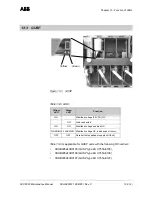
COU
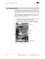
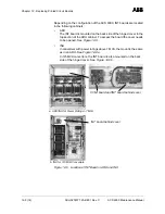
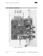
Figure 12-9 shows the INT board installed on the back side of the
right front door. Depending on the layout of the cabinet and the
configuration of the ACS 6000 the board can be mounted in a
different position.
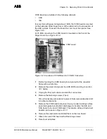
Figure 12-9 Location of INT Board in COU
1
Before touching the INT Board ground yourself at the converter frame
with a wrist strap.
2
Remove the power and ground the ACS 6000 according to section
12.1 Safety.
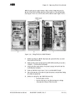
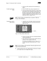
3
Unplug the fiber optic cables and the power supply connector.
4
Remove the fastening screws (13 pcs).
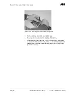
Take all necessary precautions to prevent screws and washers falling
into other components.
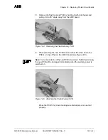
5
Remove the INT board and place it on a grounded working surface
protected against electrostatic discharges to transfer the EPLD chip
and if necessary the Pulse Pattern Flash to the new INT board. The
location of the memory chips can be seen in
Figure 12-7.
6
Transfer the memory chips.
7
Depending on the cabinet the INT board has been removed from the
following memory chips have to be transferred from the faulty to the
new board:
•
EPLD Chip and Pulse Pattern Flash if INT board
was installed in an ARU,
•
EPLD Chip if INT board was installed in an INU or
COU (INT boards used in INUs or COUs have no
Pulse Pattern Flash).


