


ABB
Chapter 12 - Replacing Printed Circuit Boards
ACS 6000 Maintenance Manual
3BHS202077 ZAB E01 Rev. C
12-5 (14)
3
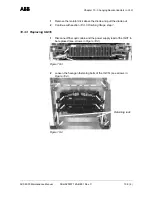
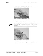
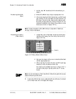
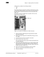
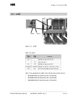
Remove the flash memory PCB by holding it with both hands and
pulling it at a 90° angle away from the AMC board.
Figure 12-4 Removing the Flash Memory PCB
4
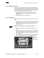
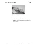
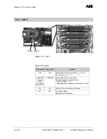
When attaching the new PCB make sure that the white dot on the
PCB is on top of that on the AMC3 board (see
Figure 12-5).
Note: Correct orientation of the new PCB is important. If attached wrongly
the new PCB will be damaged immediately when the auxiliary power is
switched on.
Figure 12-5 Attaching the Flash Memory PCB
Press the PCB firmly down making sure that all pins are inserted
properly.


