


Chapter 2 - Checking IGCTs and Diodes
ABB
2-2 (6)
3BHS202077 ZAB E01 Rev. C
ACS 6000 Maintenance Manual
Note: When checking be careful not to disconnect the fiber optic cable
while the IGCT is energized to prevent an undefined control state.
3
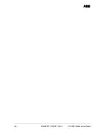
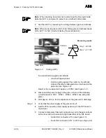
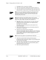
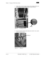
Test the IGCT by measuring the voltage between gate and cathode.
Note: When measuring be careful not to shorten gate and cathode/anode
of the IGCT. A short circuit will destroy the semiconductor.
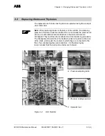
Figure 2-2
Testing IGCTs
To avoid shortening gate and cathode:
•
Use short tipped probes
•
Hold one probe against the cooler on the cathode
side and the other probe against a screw head on the
gate side (see
Figure 2-2).
Result of the measurement: approx. -20 VDC (see
Figure 2-2 ).
4
Disconnect the power supply of the gate unit (one of the following
circuit breakers in COU: -Q1041, -Q1042, -Q1043, see wiring dia-
gram).
5
Wait approx. 20 sec. for the capacitors of the gate unit to discharge.
Step 2
1
Verify that the power supply of the gate unit is off.
2
Switch off the auxiliary power supply pertaining to the INT board in
the cabinet.
3
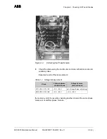
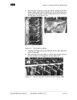
Connect a temporary fiber optic cable at one end to the gate unit and
at the other end to a permanent light transmitter of the INT board.
•
Inside ARU: connector A714 (see
Figure 2-3)
•
Inside INU: connector A712 or A713 (see
Figure 2-3)
Cathode
Gate
Measuring results:
Step 1: -20 VDC
Step 2: +0.7 VDC
Side view


