background image

ABB

ACS 6000 Maintenance Manual

3BHS202077 ZAB E01 Rev. C

2-1 (6)

Chapter 2 - Checking IGCTs and Diodes

IGCTs and diodes of phase modules can only be tested after the converter 
has been deenergized and grounded.

Danger: The ACS 6000 is a high violtage device.

Make sure that the drive has been completely deenergized and that power 
cannot be applied by accident.

Failure to do so may result in injury or death.

2.2.1

Required Tools and Accessories

To test IGCTs the following is needed:

Fiber optic cable (approx. 2 m long)

Multimeter

2.2.2

Test Procedure

The IGCT to be tested can stay in the phase module. The test is carried 
out in two steps:

Step 1

1

Deenergize and ground the ACS 6000 but leave the power supply for 
the gate units on.

2

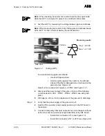
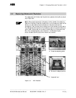
Check the IGCT for burned components. In this case the whole IGCT 
must be replaced. Check that both LEDs are on. See 

Figure 2-1 

(

Figure 2-1 depicts the horizontal fitting position of IGCTs as applied 

in 7/9 MVA phase modules).

Figure 2-1

IGCT

2.1

Safety

2.2

Checking IGCTs

LEDs

Fiber optic cable

Summary of Contents for ACS 6000

Page 1: ...ABB Switzerland Ltd All Rights Reserved ACS 6000 Medium Voltage Drives 3 to 27 MVA Service and Maintenance Manual Document No 3BHS202077 ZAB E01 Rev C Issued 21 01 2005 ABB...

Page 2: ...ndustrial property protection right Misuse in particular duplication and forwarding to third parties is not permitted This document has been checked with due care and attention However should the user...

Page 3: ...9 MVA Phase Modules 2 4 Chapter 3 Changing Diodes and Thyristors in LSU 3 1 3 1 Required Tools and Accessories 3 1 3 2 Safety 3 2 3 3 Replacing Diodes and Thyristors 3 3 Chapter 4 Changing 3 5 MVA Ph...

Page 4: ...ower NP Diode 8 12 Assembling the Stack 8 12 8 4 4 Finishing Steps 8 13 8 5 Replacing Free Wheeling Diodes 8 14 8 6 Replacing IGCTs 8 16 Chapter 9 Changing Thyristors in EXU 9 1 9 1 Required Tools and...

Page 5: ...acing an AMC3 Board 12 2 12 3 Changing the AMC3 Flash Memory 12 4 12 4 Replacing an INT Board 12 7 Transferring the EPLD Chips 12 10 Transferring the Pulse Pattern Flash 12 10 12 5 Replacing a CVMI Bo...

Page 6: ...ABB 4 4 3BHS202077 ZAB E01 Rev C ACS 6000 Maintenance Manual...

Page 7: ...nd other work on the ACS 6000 must only be carried out by qualified personnel in compliance with local regula tions Danger Do not access the ACS 6000 or work on the motor or the power cables if the dr...

Page 8: ...tenance Manual Danger Before power is applied to the drive check that Mains and motor connections are ok Auxiliary power and control cable connections are ok No tools or other foreign objects are left...

Page 9: ...Required Tools and Accessories To test IGCTs the following is needed Fiber optic cable approx 2 m long Multimeter 2 2 2 Test Procedure The IGCT to be tested can stay in the phase module The test is ca...

Page 10: ...nd the other probe against a screw head on the gate side see Figure 2 2 Result of the measurement approx 20 VDC see Figure 2 2 4 Disconnect the power supply of the gate unit one of the following circu...

Page 11: ...ABB Chapter 2 Checking IGCTs and Diodes ACS 6000 Maintenance Manual 3BHS202077 ZAB E01 Rev C 2 3 6 Figure 2 3 INT Board A712 A713 A714...

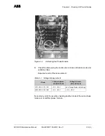
Page 12: ...ntil both LEDs on the gate unit have lighted up To test a diode the phase module needs to be disconnected from the busbar connectors Water hoses optical fibers and gate unit power supply leads can sta...

Page 13: ...n diode verification mode and suitable probes Expected result of the measurement If uncertain verify the result by checking another diode of the same phase module or of another phase module Table 2 1...

Page 14: ...Chapter 2 Checking IGCTs and Diodes ABB 2 6 6 3BHS202077 ZAB E01 Rev C ACS 6000 Maintenance Manual...

Page 15: ...nd Thyristors in LSU The tools listed below are part of the tool set ident no 3BHS130246 delivered with the ACS 6000 Spreader tool Figure 3 1 Spreader Tool reversible ratchet 100 mm extension bar 13 m...

Page 16: ...high voltage device Make sure that the cabinet has been completely deenergized and that power cannot be applied by accident Failure to do so may result in injury or death Note After switching off the...

Page 17: ...ure all at once as otherwise all semiconductors in the stack will become misaligned They must then be recentered in a time consuming procedure The misalignment results from the flexible busbar connect...

Page 18: ...the clamping pressure and then spread the spreader tool to maintain the pressure in the stack above the semiconductor to be changed Proceeding in this manner prevents the semiconductors from becoming...

Page 19: ...et By means of the adjustment bolts the wooden bar is pushed against the coolers thus pushing the coolers back into place and holden them there The semicon ductors can be centered one by one starting...

Page 20: ...Chapter 3 Changing Diodes and Thyristors in LSU ABB 3 6 6 3BHS202077 ZAB E01 Rev C ACS 6000 Maintenance Manual...

Page 21: ...o eyebolts DIN 580 M12 for lifting the phase module by means of an overhead crane Wrench with extension bar approx 80 cm and 10 mm ball end hex driver for replacing the phase module 18 mm ring spanner...

Page 22: ...e cabinet has been completely deenergized and that power cannot be applied by accident Failure to do so may result in injury or death Note After switching off the mains and after the motor has come to...

Page 23: ...ct the water hose pull the locking sleeve of the coupling towards the front of the cabinet see arrow in Figure 4 3 b Figure 4 3 Water Hose Couplings 5 Carefully cut off the cables ties which fasten th...

Page 24: ...al 7 Slide each rail under the phase module to be changed until the rail inserts properly into the bracket at the back of the module Figure 4 5 Mounting the Rails 8 Secure the rails by inserting the s...

Page 25: ...gure 4 7 The phase module will be lowered and the wheels of the module will touch the rails Required tools Wrench 80 cm extension 10 mm ball end hex driver Figure 4 7 Fastening Bolts 10 Extract the ph...

Page 26: ...CS 6000 Maintenance Manual Using the Hoist 12 Attach the hoist to the cabinet at the three connection points see circles in Figure 4 8 Figure 4 8 Attaching the Hoist 13 Attach the lifting bar to the p...

Page 27: ...e to withdraw the rails Figure 4 10 Phase Module Attached to Hoist 15 After the rails have been removed slowly lower the phase module to the floor Using a Crane 16 Screw the two eyebolts into the tapp...

Page 28: ...bolts of the phase module with MOLYKOTE type D Figure 4 12 Greasing Fastening Bolts 2 Grease the ends of the busbar stubs using grease of type RHODORSIL or SILICONPASTE 4 See arrows in Figure 4 13 Fi...

Page 29: ...Nm 8 Remove the rails 9 Connect the fiber optics and power supply cables and fix them with cable ties 10 Check each water hose coupling for damage before connection If damaged the coupling must be cha...

Page 30: ...Chapter 4 Changing 3 5 MVA Phase Modules ABB 4 10 10 3BHS202077 ZAB E01 Rev C ACS 6000 Maintenance Manual...

Page 31: ...pull out the two retaining rods Figure 5 1 Phase Module 3 Slide the clamp pressure loading gauge attached to the side of the phase module see Figure 5 1 under the clamp ring of the pressure adjusting...

Page 32: ...hol Using a fluff free cloth wipe the surfaces paying attention not to scratch the surfaces Note Do not use any grease or any electrical joint compound 7 Push the new RC IGCT into the stack 8 Tighten...

Page 33: ...lace the module on a flat surface 3 To change the NP diode the phase module needs to be turned onto the side where there are no water connections Unscrew the retaining brackets of the fastening bolts...

Page 34: ...two Wooden Beams 4 Slide the clamp pressure loading gauge under the clamp ring of the pressure adjusting bolt and loosen the bolt to release the clamp pressure of the stack see Figure 6 3 Figure 6 3...

Page 35: ...s paying attention not to scratch the surfaces Note Do not use any grease or any electrical joint compound 8 Place the new diode in the stack 9 Put the isolator disc back in its place 10 Tighten the p...

Page 36: ...Chapter 6 Changing Clamp Diodes in 3 5 MVA Phase Modules ABB 6 4 4 3BHS202077 ZAB E01 Rev C ACS 6000 Maintenance Manual...

Page 37: ...t no 3BHS130246 delivered with the ACS 6000 ACS 6000 lifting table Figure 7 1 ACS 6000 Lifting Table Wrench with extension bar approx 80 cm and 16 mm ball end hex driver for replacing the phase module...

Page 38: ...at the cabinet has been completely deenergized and that power cannot be applied by accident Failure to do so may result in injury or death Note After switching off the mains and after the motor has co...

Page 39: ...r hold a towel or cloth underneath the coupling to prevent water from getting inside the phase module or the measuring board below Figure 7 3 Protecting Cover 5 Disconnect the upper hose first and the...

Page 40: ...odule see circles in Figure 7 5 and then disconnect the fiber optic cables and the power supply leads see arrows in Figure 7 5 Figure 7 5 Disconnecting Fiber Optics and Power Supply Cables 8 Remove th...

Page 41: ...le from the cabinet Figure 7 7 Phase Module Removed from Cabinet 1 Grease the ends of the busbar stubs using grease of type RHODORSIL or SILICONPASTE 4 1 Make sure that the disconnected water hoses fi...

Page 42: ...il the coupling locks home with a click 7 Wipe off any spilled water immediately 8 Reconnect the fiber optic and power supply cables see arrows in Figure 7 5 Do not mix up the cables The denomination...

Page 43: ...30246 delivered with the ACS 6000 Spreader tool Figure 8 1 Spreader Tool Two 23 mm extra thin open end spanners Set of hex keys 10 mm combination spanner 13 mm ratcheting combination wrench reversible...

Page 44: ...clamp NP and free wheeling diodes but can remain in the cabinet to replace IGCTs Refer to Chapter 7 Changing 7 9 MVA Phase Modules for information on removing a phase module from the cabinet Refer to...

Page 45: ...er 8 Changing Diodes and IGCTs in 7 9 MVA Phase Modules ACS 6000 Maintenance Manual 3BHS202077 ZAB E01 Rev C 8 3 18 Figure 8 3 Phase Module Clamp diode NP diode Clamp diode NP diode Free wheeling diod...

Page 46: ...ge device Make sure that the cabinet has been completely deenergized and that power cannot be applied by accident Failure to do so may result in injury or death Note After switching off the mains and...

Page 47: ...fety 2 Slide the clamp pressure loading gauge under the clamp ring of the pressure adjusting bolt and remove the bolt to release the clamp pressure of the stack using the 12 mm hex socket from the too...

Page 48: ...ite end Finally remove the set screws at both ends taking care not to apply too much force Using too much force will destroy the capacitors Figure 8 6 Removing the Top Fastening Nut 4 Using the two ex...

Page 49: ...tack to create more clearance facilitating work on the diodes Figure 8 8 Removing Isolator Disc 7 Remove the fastening bolts of the uppper perforated busbar see circle in Figure 8 9 Figure 8 9 Removin...

Page 50: ...f free cloth wipe the surfaces paying attention not to scratch the surfaces Note Do not use any grease or any electrical joint compound 3 Put the new diode the perforated busbar and the isolator disk...

Page 51: ...fter the steps of section 8 4 1 Preparatory Steps have been carried out do the following 6 Remove the fastening bolts of the lower perforated busbar and turn it to the side to make room for the spread...

Page 52: ...he contact surfaces with an appropriate solvent e g alcohol Using a fluff free cloth wipe the surfaces paying attention not to scratch the surfaces Note Do not use any grease or any electrical joint c...

Page 53: ...After the steps of section 8 4 1 Preparatory Steps have been carried out do the following 1 Turn the u shaped busbar to the side for easier access to the upper NP diode Figure 8 15 Replacing NP Diodes...

Page 54: ...diode from the stack with the other hand Figure 8 17 Extracting Lower NP Diode Assembling the Stack 1 Check the contact surfaces of the new diode s and the coolers for any dirt If necessary clean the...

Page 55: ...nd lateral forces acting on the capacitors When tightening the nuts pay attention not to exceed the maximum tightening torque M8 nuts 8 Nm Exceeding the maximum value may result in damage of the capac...

Page 56: ...pressure loading gauge under the clamp ring of the pressure adjusting bolt and remove the bolt to release the clamp pressure of the stack using the 12 mm hex socket from the tool box Figure 8 18 Pres...

Page 57: ...ion not to scratch the surfaces Note Do not use any grease or any electrical joint compound 6 Place the new diode in the stack Pay attention to the correct polarity particularly when exchanging diodes...

Page 58: ...with the phase module remaining in the cabinet Note If an IGCT is faulty do not replace the semiconductor only Always replace the complete module GCT and gate unit 1 Slide the clamp pressure loading...

Page 59: ...remove the two retaining rods 5 Extract the top isolator disk 6 Lift the cooler above the faulty IGCT and extract the faulty IGCT The cooler above the upper IGCT can be lifted up by hand When extract...

Page 60: ...he guiding rails and that the contact surfaces of the semiconductor are not scratched 10 Insert the isolator disk and center it properly 11 Insert the pressure adjusting bolt by hand taking care that...

Page 61: ...EXU do the following 1 Deenergize and ground the ACS 6000 Danger The ACS 6000 is a high voltage device Make sure that the cabinet has been completely deenergized and that power cannot be applied by ac...

Page 62: ...removed from the cabinet See section 9 2 Safety 2 Cut off the cable tie securing the thyristor gate wires and remove them from the pulse transformer 3 Loosen the clamp bolts alternately until they can...

Page 63: ...a nylon sponge carefully abrade the mating surfaces by applying circular movements Take special care not to expose the copper when abrading Wipe the abraded semiconductor surfaces clean with methanol...

Page 64: ...th bolts alternately first turning them half a turn each then less until the desired compression force is reached see Figure 9 9 for the correct value 6 Connect the gate wires to the pulse transformer...

Page 65: ...e support in order to be able to remove the thyristor see Figure 9 8 Cut off the cable tie securing the thyristor gate wires and remove them from the pulse transformer 3 Loosen the clamp bolts alterna...

Page 66: ...ble cloth and apply a thin layer of heat conducting compound G 322 L on the mating surfaces with a rubber trowel 9 4 3 Mounting a New Thyristor 1 Push the semiconductor into the plastic guide Pay atte...

Page 67: ...anty period has expired Figure 9 9 Deflection Diagram 9 5 Deflection Diagram Direct excitation 5STP 1842H 0 10 20 30 40 50 60 0 07 0 08 0 09 0 1 0 11 0 12 0 13 Clamp type SLZD 117 Force 45 kN Deflecti...

Page 68: ...Chapter 9 Changing Thyristors in EXU ABB 9 8 8 3BHS202077 ZAB E01 Rev C ACS 6000 Maintenance Manual...

Page 69: ...ound the ACS 6000 Danger The ACS 6000 is a high voltage device Make sure that the cabinet has been completely deenergized and that power cannot be applied by accident Failure to do so may result in in...

Page 70: ...of the pressure adjusting bolt and remove the bolt to release the clamp pressure of the stack using the 12 mm 1 2 hex socket from the tool box Figure 10 1 Top View of VLU 10 3 2 Replacing Upper Diode...

Page 71: ...e the diode and pull the diode out 2 Continue with section 10 3 5 Finishing Steps step 1 10 3 3 Replacing IGCTs 1 Disconnect fiber optic cable and the power supply lead of the IGCT to be replaced see...
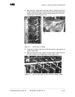
Page 72: ...T is free Figure 10 5 4 Remove the isolator disk and the diode above the IGCT 5 Pull out the faulty IGCT 6 In case the new IGCT is not fitted with retaining clamps and guides see Figure 10 6 remove th...

Page 73: ...s After the new component has been inserted into the stack proceed as follows 1 Thoroughly clean the contact surfaces of the new semiconductor and the adjacent components with an appropriate solvent e...

Page 74: ...adjusting bolt until the clamp pressure loading gauge is released 6 Refit the clamp loading gauge in its storage place 7 If a defective part has to be returned to ABB particularly if it is still unde...

Page 75: ...6000 Danger The ACS 6000 is a high voltage device Make sure that the cabinet has been completely deenergized and that power cannot be applied by accident Failure to do so may result in injury or deat...

Page 76: ...e replacement of IGCTs is explained using the example of size 1 of the CBU Although the space in this type of CBU is very narrow the IGCTs can be replaced from the front of the cabinet 1 Check that th...

Page 77: ...ove Therefore it is recommended to remove the clamp head to facilitate work The clamp disk and the isolators below the disk springs of the clamp head can also only be removed after the clamp head has...

Page 78: ...3BHS202077 ZAB E01 Rev C ACS 6000 Maintenance Manual 4 Remove the fastening bolts of the IGCT The bolts require a 10 mm socket Figure 11 4 Fastening Bolts 5 Remove the faulty IGCT Figure 11 5 IGCT Re...

Page 79: ...nto place The two pins on the cooler must insert properly into the holes of the mounting bracket of the IGCT see Figure 11 5 4 Reinstall the components above the IGCT 5 Adjust the clamping pressure Ti...

Page 80: ...Chapter 11 Changing IGCTs in DIU ABB 11 6 6 3BHS202077 ZAB E01 Rev C ACS 6000 Maintenance Manual...

Page 81: ...y Refer to the wiring diagrams to identify the circuit breaker Note Do not touch printed circuit boards or other sensitive components without applying static sensitive handling precautions Static elec...

Page 82: ...Chapter 12 Replacing Printed Circuit Boards ABB 12 2 14 3BHS202077 ZAB E01 Rev C ACS 6000 Maintenance Manual Figure 12 1 AMC Board 12 2 Replacing an AMC3 Board...

Page 83: ...the AMC3 board ground yourself at the converter frame with a wrist strap 2 Remove the power and ground the ACS 6000 according to section Chapter 1 Introduction and Safety 3 Unplug the fiber optic cabl...

Page 84: ...still under warranty follow the procedures as stated in the Warranty Directives this is recommended even if the warranty has expired The application control software and the parameter settings are sav...

Page 85: ...e 12 4 Removing the Flash Memory PCB 4 When attaching the new PCB make sure that the white dot on the PCB is on top of that on the AMC3 board see Figure 12 5 Note Correct orientation of the new PCB is...

Page 86: ...sh Memory PCB 5 Put the defective board into an antistatic bag 6 Power up the drive and confirm its proper functioning 7 If the defective board has to be returned to ABB particularly if the component...

Page 87: ...ABB Chapter 12 Replacing Printed Circuit Boards ACS 6000 Maintenance Manual 3BHS202077 ZAB E01 Rev C 12 7 14 Figure 12 7 INT Board 12 4 Replacing an INT Board b EPLDs c Pulse Pattern Flash a...

Page 88: ...top section of the ARU cabinet To access the board the cover needs to be opened See Figure 12 8 INU In converters with power ratings above 7 MVA the mount is the same as in an ARU See Figure 12 8 a I...

Page 89: ...power supply connector 4 Remove the fastening screws 13 pcs Take all necessary precautions to prevent screws and washers falling into other components 5 Remove the INT board and place it on a grounde...

Page 90: ...of the EPLD chip is important If attached wrongly it will be damaged Transferring the Pulse Pattern Flash 1 Unlock the cover of the flash socket by pushing the middle section away from the notch see a...

Page 91: ...rify the connections by comparing them with the corresponding wiring diagram 12 Put the defective board into an antistatic bag 13 Power up the drive and check the version number of the EPLDs and the P...

Page 92: ...Chapter 12 Replacing Printed Circuit Boards ABB 12 12 14 3BHS202077 ZAB E01 Rev C ACS 6000 Maintenance Manual Figure 12 11 CVMI Board 12 5 Replacing a CVMI Board SCA Board SVA Board...

Page 93: ...certers 1 Before touching the CVMI board ground yourself at the converter frame with a wrist strap 2 Remove the power and ground the ACS 6000 according to section 12 1 Safety 3 Unplug the fiber optic...

Page 94: ...corresponding wiring diagram 10 Put the defective board into an antistatic bag 11 Power up the drive and confirm its proper functioning 12 If the defective board has to be returned to ABB particularl...

Page 95: ...ABB ACS 6000 Maintenance Manual 3BHS202077 ZAB E01 Rev C 13 1 6 Chapter 13 Function of LEDs Figure 13 1 AMC3 Board 13 1 AMC Board R P T2 S1 S0 F M T1 S3 S4...

Page 96: ...LED LED Color Function Run green Always OFF Fault red Not used ON when booting P green Supply OK M green Not used ON when booting T1 yellow ON receiving data on DDCS channel 0 T2 yellow ON receiving...

Page 97: ...ABB Chapter 13 Function of LEDs ACS 6000 Maintenance Manual 3BHS202077 ZAB E01 Rev C 13 3 6 Figure 13 2 INT Board 13 2 INT Board V561 V562 V563 V564 V565 V566 V567 V568...

Page 98: ...w ON INU modulating Y562 yellow ON tripped depending on the fault class the MCB is opened or remains closed Y563 yellow ON tripped pulses are removed Y564 yellow Always OFF Y565 yellow ON tripped with...

Page 99: ...05243R0105 GUSP type KU C755AE105 3BHB005243R0106 GUSP type KU C755AE106 3BHB005243R0107 GUSP type KU C755AE107 13 3 GUSP Table 13 5 LEDs Yellow LED Green LED Function ON Stabilized voltage 20 VDC OK...

Page 100: ...nction ON ON Output stage functions correctly Uout 10 V No overload Uout 17 V FLASHING if output voltage decreases below 10 V FLASHING Output stage functions correctly Overload present or output short...

Page 101: ...4 1 2 Tightening Torque for Pumps WCU Type 29 and 52 1 see Figure 14 2 to locate the parts 2 for lubricated threads 14 1 Water Cooling Unit Table 14 1 Tightening Torques Part Thread Diameter Tightenin...

Page 102: ...omponents Item No Description Item No Description 101 Pump casing 68 3 Cover plate 163 Discharge cover 801 Flanged motor 182 2 2 Pump foot 901 1 5 Hex head bolt 210 Shaft 902 1 Stud 230 Impeller 903 1...

Page 103: ...25 M12 55 M12 24 x 13 x 2 73 x 40 x 1 5 24 33 Nm 32 M16 65 M16 30 x 73 x 3 84 x 48 x 1 5 60 80 Nm 40 M16 65 M16 30 x 73 x 3 92 x 57 x 1 5 60 80 Nm 50 M16 70 M16 30 x 73 x 3 107 x 66 x 1 5 60 80 Nm 65...

Page 104: ...Chapter 14 Tightening Torques and Threaded Connections ABB 14 4 4 3BHS202077 ZAB E01 Rev C ACS 6000 Maintenance Manual...

Reviews: