Chapter 12 - Replacing Printed Circuit Boards
ABB
12-10 (14)
3BHS202077 ZAB E01 Rev. C
ACS 6000 Maintenance Manual
1 Put the new INT board next to the board being re-
placed.
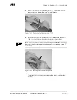
Transferring the EPLD
Chips
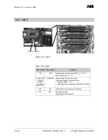
2 Extract the EPLD chip using an appropriate tool.
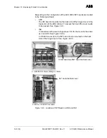
3 When inserting the EPLD chip into the new INT board
pay attention to the orientation and the allocation of
the chips. The dot on the chip must be aligned with
the arrow on the socket (see arrows in
Figure 12-7 b).
Allocate the EPLDs according to the numbers on the
labels (see circles in
Figure 12-7 b).
Note: Correct orientation of the EPLD chip is important. If attached
wrongly it will be damaged.
Transferring the Pulse
Pattern Flash
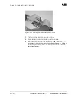
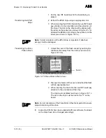
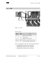
1 Unlock the cover of the flash socket by pushing the
middle section away from the notch (see arrows in
Figure 12-10 b).
Figure 12-10 Pulse Pattern Flash Cover
2 Flip open the halves of the cover and extract the flash
with an appropriate tool.
3 When inserting the flash into the new INT board pay
attention to the orientation of the chip.
The chip must orientated as shown in
Figure 12-7 c.
The dot on the chip must be next to the "1" on the
board.
Note: Correct orientation of the Pulse Pattern Flash is important to ensure
proper functioning of the drive.
8
In case the EPLDs have been updated with new software, the labels
on the chips have to be changed accordingly.
Notch

