Chapter 8 - Changing Diodes and IGCTs in 7/9 MVA Phase Modules
ABB
8-16 (18)
3BHS202077 ZAB E01 Rev. C
ACS 6000 Maintenance Manual
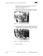
12
Remount the phase module in the cabinet following section
7.3
Installing a Phase Module.
13
If a defective part has to be returned to ABB, particularly if it is still
under warranty, follow the procedures as stated in the Warranty
Directive (this is recommended even if the warranty period has
expired).
IGCTs can be replaced with the phase module remaining in the cabinet.
Note: If an IGCT is faulty do not replace the semiconductor only. Always
replace the complete module (GCT and gate unit).
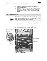
1
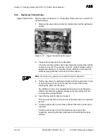
Slide the clamp pressure loading gauge under the clamp ring of the
pressure adjusting bolt and remove the bolt to release the clamp
pressure of the stack using the 12 mm ½" hex socket from the tool
box.
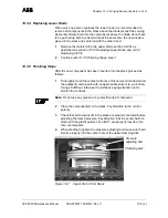
The location of the gauge can be seen in
Figure 8-2.
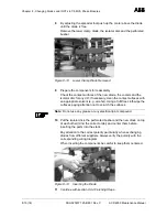
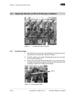
2
Remove the perspex cover on top of the phase module.
Figure 8-21
Phase Module
8.6
Replacing IGCTs
Pressure adjusting bolt
Pressure loading gauge
Perspex cover
Retaining rod
Fiber optic cable
Power supply
Isolator disk
Clamp ring


