


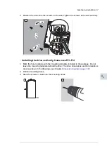


2.
Drill the mounting holes.
3.
Start the screws or bolts into the mounting holes.
4.
Position the drive onto the screws on the wall. Lift the drive with another person as it is
heavy.
5.
Tighten the screws in the wall securely.
50 Mechanical installation
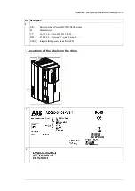
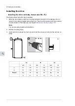
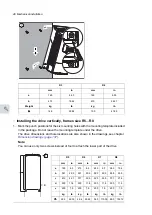
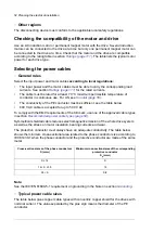
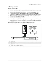
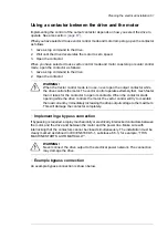
Installing the drive vertically, frames size
R5…R8
1. Mark the punch positions for the six mounting holes with the mounting template
included in the package. Do not leave the mounting template under the drive.
The drive dimensions and hole locations are also shown in the drawings, see
chapter
Dimension drawings
on page
149
.
Note:
You can use only two screws instead of four to attach the lower part of the
drive.
2. Drill the mounting holes.
3. Start the screws or bolts into the mounting holes.
4. Position the drive onto the screws on the wall. Lift the drive with another person
as it is heavy.
5. Tighten the screws in the wall securely.
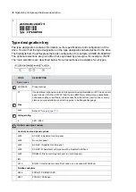
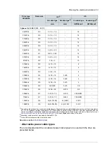
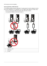
R5
R6
R7
R8
mm
in
mm
in
mm
in
mm
in
a
612 24.1
571 22.5 623 24.5 701 27.6
b
581 22.9
531 20.9 583 22.9 658 25.9
c
160 6.3
213
8.4
245
9.7 263 10.4
d
300
11.8
300 11.8 300 11.8 300 11.8
e
200
7.9
200
7.9
200
7.9 200
7.9
kg
lb
kg
lb
kg
lb
kg
lb
28
62
45
99
55
121
70
154
× 4
1
3
× 2
× 2
4
2
5
M8
50 Mechanical installation
Installing the drive vertically, frames size
R5…R8
1. Mark the punch positions for the six mounting holes with the mounting template
included in the package. Do not leave the mounting template under the drive.
The drive dimensions and hole locations are also shown in the drawings, see
chapter
Dimension drawings
on page
149
.
Note:
You can use only two screws instead of four to attach the lower part of the
drive.
2. Drill the mounting holes.
3. Start the screws or bolts into the mounting holes.
4. Position the drive onto the screws on the wall. Lift the drive with another person
as it is heavy.
5. Tighten the screws in the wall securely.
R5
R6
R7
R8
mm
in
mm
in
mm
in
mm
in
a
612 24.1
571 22.5 623 24.5 701 27.6
b
581 22.9
531 20.9 583 22.9 658 25.9
c
160 6.3
213
8.4
245
9.7 263 10.4
d
300
11.8
300 11.8 300 11.8 300 11.8
e
200
7.9
200
7.9
200
7.9 200
7.9
kg
lb
kg
lb
kg
lb
kg
lb
28
62
45
99
55
121
70
154
× 4
1
3
× 2
× 2
4
2
5
M8
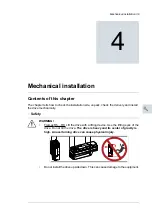
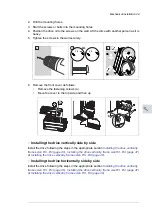
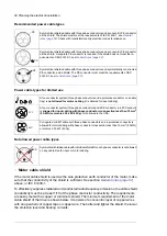
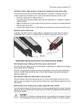
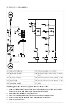
6.
Remove the front cover as follows:
•
Remove the fastening screws (a).
•
Move the cover to the top side and then up
Mechanical installation 51
6. Remove the front cover as follows:
•
Remove the fastening screws (a).
•
Move the cover to the top side and then up.
Installing the drive vertically side by side
Install the drive following the steps in the appropriate section
Installing the drive
vertically, frames size R0…R2
(on page
47
),
Installing the drive vertically, frame size
R3...R4
(on page
49
) or
Installing the drive vertically, frames size R5…R8
(on page
50
).
Instructions for flange mounting are delivered with the flange mounting kit:
Flange
mounting quick guide for frames R6 to R8
(3AXD50000019099 [English]). For more
information on flange mounting, see
Flange mounting supplement
(3AXD50000019100 [English]).
6a
6a
Mechanical installation 51
6. Remove the front cover as follows:
•
Remove the fastening screws (a).
•
Move the cover to the top side and then up.
Installing the drive vertically side by side
Install the drive following the steps in the appropriate section
Installing the drive
vertically, frames size R0…R2
(on page
47
),
Installing the drive vertically, frame size
Installing the drive vertically, frames size R5…R8
Flange mounting
Instructions for flange mounting are delivered with the flange mounting kit:
mounting quick guide for frames R6 to R8
(3AXD50000019099 [English]). For more
information on flange mounting, see
Flange mounting supplement
(3AXD50000019100 [English]).
6a
6a
Mechanical installation 51
6. Remove the front cover as follows:
•
Remove the fastening screws (a).
•
Move the cover to the top side and then up.
Installing the drive vertically side by side
Install the drive following the steps in the appropriate section
Installing the drive
vertically, frames size R0…R2
(on page
47
),
Installing the drive vertically, frame size
R3...R4
(on page
49
) or
Installing the drive vertically, frames size R5…R8
(on page
50
).
Flange mounting
Instructions for flange mounting are delivered with the flange mounting kit:
mounting quick guide for frames R6 to R8
(3AXD50000019099 [English]). For more
information on flange mounting, see
(3AXD50000019100 [English]).
6a
6a
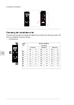
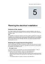
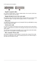
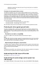
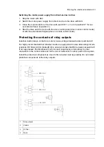
■
Installing the drive vertically side by side
Install the drive following the steps in the appropriate section
Installing the drive vertically,
,
Installing the drive vertically, frame size R3...R4 (page 47)
or
Installing the drive vertically, frames size R5…R8 (page 48)
.
■
Installing the drive horizontally side by side
Install the drive following the steps in the appropriate section
Installing the drive vertically,
,
Installing the drive vertically, frame size R3...R4 (page 47)
or
Installing the drive vertically, frames size R5…R8 (page 48)
.
Mechanical installation 49
10
Summary of Contents for ACQ80-04 Series
Page 1: ...ABB DRIVES FOR WATER ACQ80 04 drives 0 75 to 160 kW 1 0 to 215 hp Hardware manual...
Page 2: ......
Page 4: ......
Page 18: ...18...
Page 24: ...24...
Page 38: ...38...
Page 50: ...50...
Page 64: ...64...
Page 98: ...98...
Page 110: ...110...
Page 140: ...Frame R3 IP20 140 Dimension drawings...
Page 146: ...146...
Page 162: ...162...
Page 168: ......


