


7. Prepare the ends of the input power cable and motor cable as illustrated in the figure. If
you use aluminum cables, put grease to the peeled aluminum cable before connecting it to
the drive. Two different motor cable types are shown in the figures (7a, 7b).
Note:
The bare shield is grounded 360 degrees. Mark the pigtail made from the shield as a PE
conductor with yellow-and-green color.
Electrical installation 87
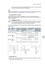
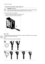
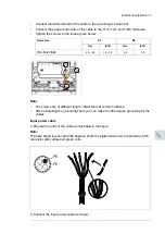
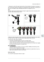
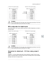
Motor cable
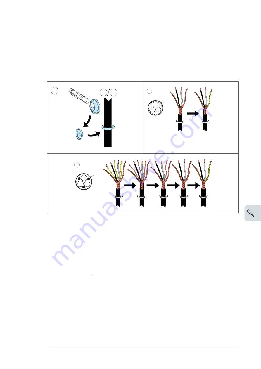
6. Cut an adequate hole into the rubber grommet. Slide the grommet onto the cable.
7. Prepare the ends of the input power cable and motor cable as illustrated in the
figure. If you use aluminum cables, put grease to the peeled aluminum cable
before connecting it to the drive. Two different motor cable types are shown in the
figures (7a, 7b).
Note:
The bare shield will be grounded 360 degrees. Mark the pigtail made from
the shield as a PE conductor with yellow-and-green color.
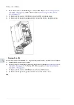
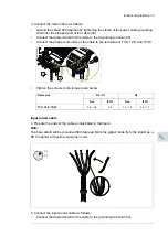
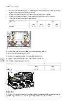
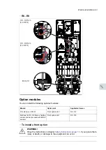
8. Slide the cables through the holes of the lead-through plate and attach the
grommets to the holes (the motor cable to the right and the input power cable to
the left).
9. Connect the motor cable as follows:
•
Ground the shield 360 degrees under the grounding clamps.
•
Connect the twisted shield of the cable to the grounding terminal (9a).
•
Connect the phase conductors of the cable to terminals T1/U, T2/V and T3/W.
Tighten the screws to the torque given in the figure (9b).
7a
PE
6
7a 7b
PE
7b
Electrical installation 87
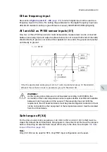
Motor cable
6. Cut an adequate hole into the rubber grommet. Slide the grommet onto the cable.
7. Prepare the ends of the input power cable and motor cable as illustrated in the
figure. If you use aluminum cables, put grease to the peeled aluminum cable
before connecting it to the drive. Two different motor cable types are shown in the
figures (7a, 7b).
Note:
The bare shield will be grounded 360 degrees. Mark the pigtail made from
the shield as a PE conductor with yellow-and-green color.
8. Slide the cables through the holes of the lead-through plate and attach the
grommets to the holes (the motor cable to the right and the input power cable to
the left).
9. Connect the motor cable as follows:
•
Ground the shield 360 degrees under the grounding clamps.
•
Connect the twisted shield of the cable to the grounding terminal (9a).
•
Connect the phase conductors of the cable to terminals T1/U, T2/V and T3/W.
Tighten the screws to the torque given in the figure (9b).
7a
PE
6
7a 7b
PE
7b
Electrical installation 87
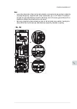
Motor cable
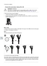
6. Cut an adequate hole into the rubber grommet. Slide the grommet onto the cable.
7. Prepare the ends of the input power cable and motor cable as illustrated in the
figure. If you use aluminum cables, put grease to the peeled aluminum cable
before connecting it to the drive. Two different motor cable types are shown in the
figures (7a, 7b).
Note:
The bare shield will be grounded 360 degrees. Mark the pigtail made from
the shield as a PE conductor with yellow-and-green color.
8. Slide the cables through the holes of the lead-through plate and attach the
grommets to the holes (the motor cable to the right and the input power cable to
the left).
9. Connect the motor cable as follows:
•
Ground the shield 360 degrees under the grounding clamps.
•
Connect the twisted shield of the cable to the grounding terminal (9a).
•
Connect the phase conductors of the cable to terminals T1/U, T2/V and T3/W.
Tighten the screws to the torque given in the figure (9b).
7a
PE
6
7a 7b
PE
7b
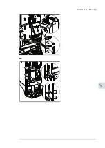
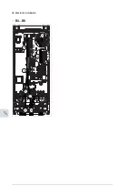
8. Slide the cables through the holes of the lead-through plate and attach the grommets to
the holes (the motor cable to the right and the input power cable to the left).
9. Connect the motor cable as follows:
•
Ground the shield 360 degrees under the grounding clamps.
•
Connect the twisted shield of the cable to the grounding terminal (9a).
•
Connect the phase conductors of the cable to terminals T1/U, T2/V and T3/W. Tighten
the screws to the torque given in the figure (9b).
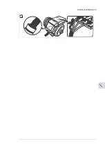
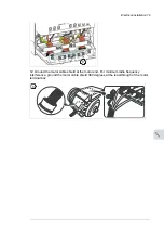
Note:
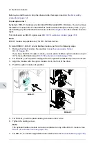
Frame R8 only:
•
If you connected the connector to only one conductor, ABB recommends to put the
conductor under the upper pressure plate.
•
The connectors are detachable, but ABB recommends not to detach them. If you do,
detach and reinstall the connectors as follows.
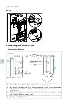
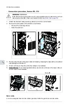
Input power cable
10. Connect the input power cable as in step
Electrical installation 81
11
Summary of Contents for ACQ80-04 Series
Page 1: ...ABB DRIVES FOR WATER ACQ80 04 drives 0 75 to 160 kW 1 0 to 215 hp Hardware manual...
Page 2: ......
Page 4: ......
Page 18: ...18...
Page 24: ...24...
Page 38: ...38...
Page 50: ...50...
Page 64: ...64...
Page 98: ...98...
Page 110: ...110...
Page 140: ...Frame R3 IP20 140 Dimension drawings...
Page 146: ...146...
Page 162: ...162...
Page 168: ......


