


Note:
•
Leave the other ends of the control cable shields unconnected or ground them indirectly
via a high-frequency capacitor with a few nanofarads, eg, 3.3 nF / 630 V. The shield
can also be grounded directly at both ends if they are
in the same ground line
with no
significant voltage drop between the end points.
•
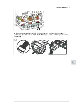
Keep any signal wire pairs twisted as close to the terminals as possible. Twisting the
wire with its return wire reduces disturbances caused by inductive coupling.
■
R0...R2
100 Electrical installation
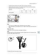
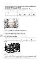
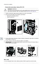
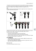
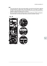
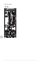
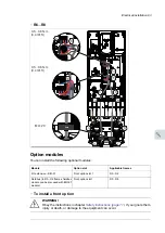
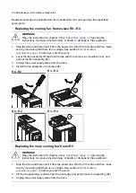
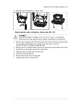
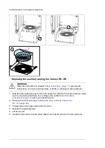
9. Route the cable as shown in the figures on pages
100
(R0…R2 and R3...R5)
and
101
(R6…R8).
10. Connect the conductors to the appropriate terminals of the control board and
tighten to 0.5…0.6 N·m (0.4 lbf·ft).
11. Tie all control cables to the provided cable tie mounts.
Note:
• Leave the other ends of the control cable shields unconnected or ground them
indirectly via a high-frequency capacitor with a few nanofarads, eg, 3.3 nF / 630 V.
The shield can also be grounded directly at both ends if they are
in the same
ground line
with no significant voltage drop between the end points.
• Keep any signal wire pairs twisted as close to the terminals as possible. Twisting
the wire with its return wire reduces disturbances caused by inductive coupling.
R3...R5
R0…R2
9
11
11
3
5
6
8
9
7
10
R0…R2: 0.5…0.6 N·m (0.4 lbf·ft)
R3: 0.5…0.6 N·m (0.4 lbf·ft)
3
4
5
6
7
8
9
9
4
8
5
6
Electrical installation 91
11
Summary of Contents for ACQ80-04 Series
Page 1: ...ABB DRIVES FOR WATER ACQ80 04 drives 0 75 to 160 kW 1 0 to 215 hp Hardware manual...
Page 2: ......
Page 4: ......
Page 18: ...18...
Page 24: ...24...
Page 38: ...38...
Page 50: ...50...
Page 64: ...64...
Page 98: ...98...
Page 110: ...110...
Page 140: ...Frame R3 IP20 140 Dimension drawings...
Page 146: ...146...
Page 162: ...162...
Page 168: ......


