


88 Electrical installation
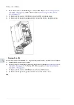
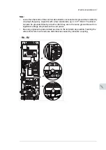
Notes for frame R8
• If you connect only one conductor to the connector, we recommend that you put it
under the upper pressure plate.
• The connectors are detachable but we do not recommend that you detach them.
If you do, detach and reinstall the connectors as follows.
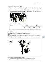
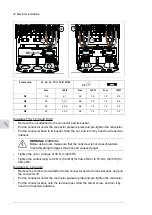
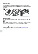
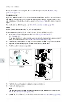
Input power cable
10. Connect the input power cable as in step
9
. Use terminals L1, L2 and L3.
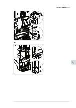
Terminals T1/U, T2/V and T3/W
•
Remove the nut that attaches the connector to its busbar.
•
Put the conductor under the connector pressure plate and pre-tighten the
conductor.
•
Put the connector back to its busbar. Start the nut, and turn it at least two
rotations by hand.
WARNING!
Before using tools, make sure that the nut/screw is not cross-
threading. Cross-threading will damage the drive and cause danger.
•
Tighten the nut to a torque of 30 N·m (22 lbf·ft).
•
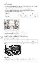
Tighten the conductor(s) to 40 N·m (30 lbf·ft) for frame R8 or to 70 N·m
(52 lbf·ft) for frame R8.
8
M5×25/35
Frame size
L1, L2, L3, T1/U, T2/V, T3/W
PE,
N·m
lbf·ft
N·m
N·m
N·m
lbf·ft
R6
30
22.1
9.8
7.2
R7
40
29.5
9.8
7.2
R8
40
29.5
9.8
7.2
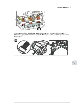
8
9a
10a
10b
9b
88 Electrical installation
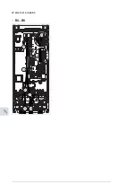
Notes for frame R8
• If you connect only one conductor to the connector, we recommend that you put it
under the upper pressure plate.
• The connectors are detachable but we do not recommend that you detach them.
If you do, detach and reinstall the connectors as follows.
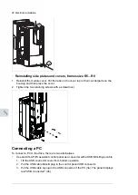
Input power cable
10. Connect the input power cable as in step
9
. Use terminals L1, L2 and L3.
Terminals T1/U, T2/V and T3/W
•
Remove the nut that attaches the connector to its busbar.
•
Put the conductor under the connector pressure plate and pre-tighten the
conductor.
•
Put the connector back to its busbar. Start the nut, and turn it at least two
rotations by hand.
WARNING!
Before using tools, make sure that the nut/screw is not cross-
threading. Cross-threading will damage the drive and cause danger.
•
Tighten the nut to a torque of 30 N·m (22 lbf·ft).
•
Tighten the conductor(s) to 40 N·m (30 lbf·ft) for frame R8 or to 70 N·m
(52 lbf·ft) for frame R8.
8
M5×25/35
Frame size
L1, L2, L3, T1/U, T2/V, T3/W
PE,
N·m
lbf·ft
N·m
N·m
N·m
lbf·ft
R6
30
22.1
9.8
7.2
R7
40
29.5
9.8
7.2
R8
40
29.5
9.8
7.2
8
9a
10a
10b
9b
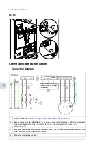
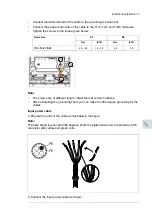
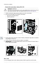
PE
L1, L2, L3, T1/U, T2/V, T3/W
Frame size
lbf·ft
N·m
lbf·ft
N·m
lbf·ft
N·m
0.9
1.2
1.6
2.2
4.1
5.6
R5
0.9
1.2
7.2
9.8
22.1
30
R6
0.9
1.2
7.2
9.8
29.5
40
R7
0.9
1.2
7.2
9.8
29.5
40
R8
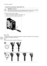
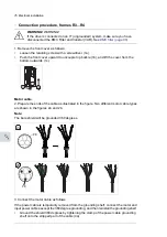
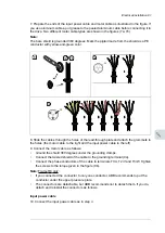
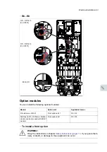
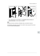
Terminals T1/U, T2/V and T3/W
•
Remove the nut attached to the connector and its busbar.
•
Put the conductor under the connector pressure plate and pre-tighten the conductor.
•
Put the connector back to its busbar. Start the nut, and turn it by hand to at least two
rotations.
WARNING!
WARNING!
Before using tools, make sure that the nut/screw is not cross-threaded.
Cross-threading damages the drive and causes danger.
•
Tighten the nut to a torque of 30 N·m (22 lbf·ft).
•
Tighten the conductor(s) to 40 N·m (30 lbf·ft) for frame R8 or to 70 N·m (52 lbf·ft) for
frame R8.
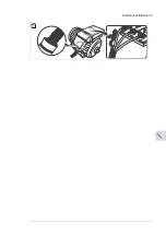
Terminals L1, L2 and L3
•
Remove the combi screw attached to the connector and to its terminal post, and pull
the connector off.
•
Put the conductor under the connector pressure plate and pre-tighten the conductor.
•
Put the connector back onto the terminal post. Start the combi screw, and turn it by
hand to at least two rotations.
82 Electrical installation
Summary of Contents for ACQ80-04 Series
Page 1: ...ABB DRIVES FOR WATER ACQ80 04 drives 0 75 to 160 kW 1 0 to 215 hp Hardware manual...
Page 2: ......
Page 4: ......
Page 18: ...18...
Page 24: ...24...
Page 38: ...38...
Page 50: ...50...
Page 64: ...64...
Page 98: ...98...
Page 110: ...110...
Page 140: ...Frame R3 IP20 140 Dimension drawings...
Page 146: ...146...
Page 162: ...162...
Page 168: ......


