


■
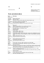
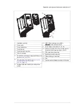
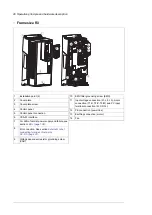
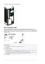
Frame R4…R8
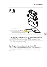
The layout of a frame R6 drive is presented below. The frame sizes R7…R8 is similar but
have a different structure.
2
3
4
5
6
7
8
11
12
13
10
10
3
16
15
1
9
12
PE
17
14
1
Voltage dependent resistor ground screw (VAR),
arranged below the control tray.
11
Two EMC filter ground screws, one arranged
below the control tray bracket and the other ar-
ranged on the left and above the protective cov-
er.
12
Protective cover. Below the protective cover: in-
put voltage connection (L1, L2, L3), motor con-
nection (T1/U, T2/V, T3/W) and DC connection
(UDC+, UDC-).
13
PE connection (power line)
14
Earthing connection (motor)
15
A primary fan
16
Auxiliary fan
17
Installation point (2 points on the top and 2 points
on the bottom of the frame body)
1
Cover plate
2
Lifting hole
3
Basic control panel
4
Control panel connection
5
CCA-01 interface
6
For LED of normal power supply and failure, see
section
7
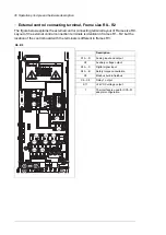
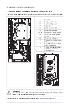
I/O connection. See section
connection terminals, frames R6…R8 (page 32)
8
Cable bundle installation position of I/O cable
9
Mechanical support clamp of I/O cable
10
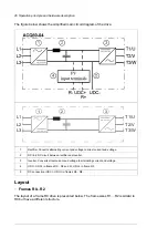
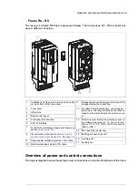
Overview of power and control connections
The logical diagram below shows the power connections and control interfaces of the drive.
Operation principle and hardware description 29
Summary of Contents for ACQ80-04 Series
Page 1: ...ABB DRIVES FOR WATER ACQ80 04 drives 0 75 to 160 kW 1 0 to 215 hp Hardware manual...
Page 2: ......
Page 4: ......
Page 18: ...18...
Page 24: ...24...
Page 38: ...38...
Page 50: ...50...
Page 64: ...64...
Page 98: ...98...
Page 110: ...110...
Page 140: ...Frame R3 IP20 140 Dimension drawings...
Page 146: ...146...
Page 162: ...162...
Page 168: ......


