For further information on protective function, error indication and diagnosis, please refer to the
AC500 documentation.
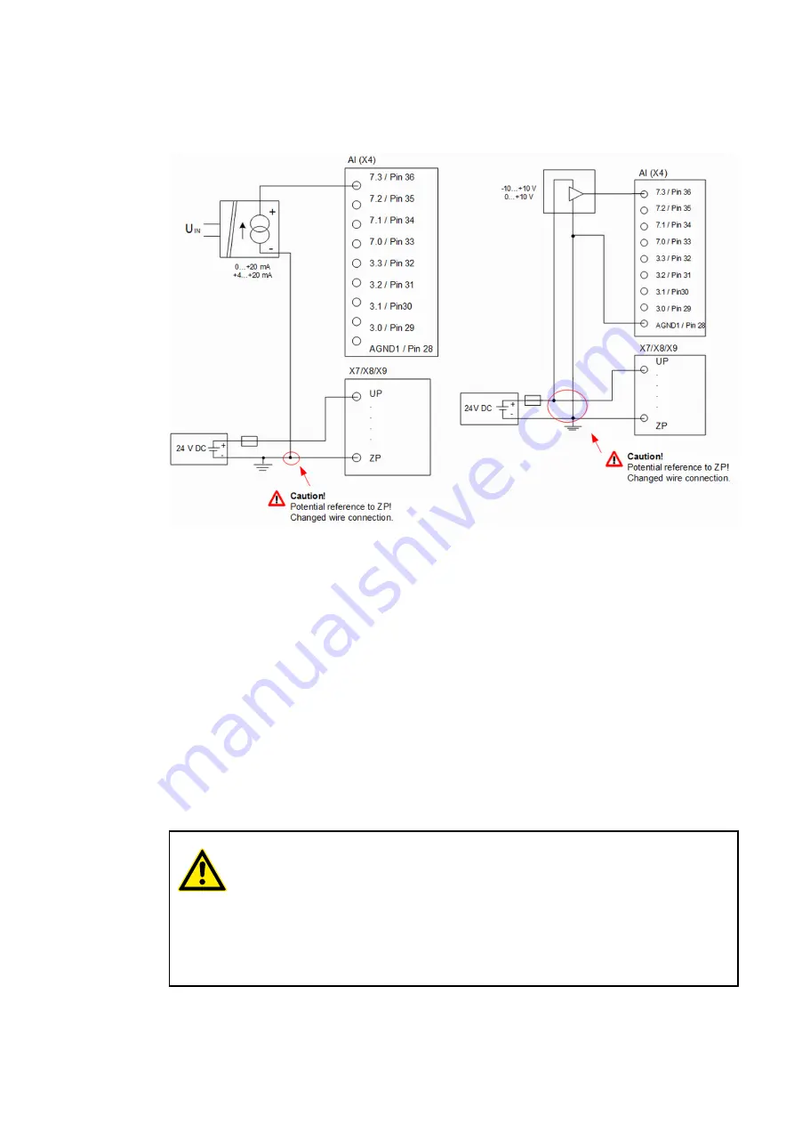
Fig. 30: Connection of current sensors 0 ... 20 mA to the analog inputs
Please note that in the example the 0 V supply (ZP) must be used as reference potential.
For further information on protective functions, error indication and diagnosis, please refer to the
AC500 documentation.
Differential inputs are very useful when applying analog sensors with non-isolated installation at
the site (e.g. if the minus terminal is earthed on site). The measurement via differential inputs
considerably improves the measuring accuracy and prevents earth loops.
When configuring differential inputs, always two adjacent analog channels belong together (e.g.
the channels 3.0 and 3.1). In this case, both channels are configured according to the desired
operating mode. The channel with the lower channel number must be the one with the even
number (e.g. channel 3.0).
The converted analog value is available at the odd channel (e.g. channel 3.1) and can be deter-
mined by means of the Automation Builder. The analog value is calculated by subtracting the
input values: input value at the channel with the higher channel number minus input value on
channel with lower channel number.
CAUTION!
Risk of faulty measurements!
The minus pole at the sensors must not have too much potential difference with
respect to ZP (max.
±
1 V within the full signal range).
–
Ensure that the potential difference never exceeds
±
1 V.
–
No change to the wiring is necessary. The connection of the sensor corre-
sponds to the one of the existing device 07KT98.
For further information on protective function, error indication and diagnosis, please refer to the
AC500 documentation.
Measuring
range (active
sensors with
external supply)
Measuring
ranges
±
10 V /
0 ... 10 V as dif-
ferential inputs
AC31 Adapters
Replacement devices: CPU > Replacement device 07KT9x-AD
2018/09/24
3ADR010122, 8, en_US
38


