9
CAUTION: Before proceeding with communication interface connection, verify
the controller’s actual communication interface type. For devices with OLED
display, the interface type will be briefl y (for about 2 seconds) displayed on
the banner screen when power is applied. If your instrument does not have
a display, the communication interface type can be identifi ed by briefl y
pressing the multi-function button and monitoring status LED response
(see Section 6.5).
Communication Settings for RS-232/RS-485 communication interface The default baud
rate is 9600 baud (user-selected; see Section 5, Specifi cations).
Stop bit: ...............................
1
Data bits: ...............................
8
Parity: ...............................
None
Flow Control: ...............................
None
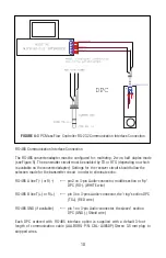
RS-232 Communication Interface Connection
Crossover connection must be established:
HOST PC RS-232 RX
Controller (RS-232 TX)
(pin 2 on the host PC DB9 connector) ------ pin 3 (Ring) of the 3-pin stereo jack connector (TX+)
HOST PC RS-232 TX
Controller (RS-232 RX)
(pin 3 on the host PC DB9 connector) ------ pin 2 (Tip) of the 3-pin stereo jack connector (RX-)
HOST PC RS-232 SIGNAL GND Controller (Digital GND)
(pin 5 on the host PC DB9 connector) ------ pin 1 (Sleeve) of the 3-pin stereo jack connector
Each DPC ordered with RS-232 interface option is supplied with default crossover 1.5- foot
long communication cable (AALBORG P/N: CBL-A232) DB9 female to stereo 3.5 mm Plug.
If custom length cable is required, it can be assembled using the connection diagram
shown in
Figure 4.
Summary of Contents for DPC
Page 6: ...2...
Page 120: ...116 APPENDIX I COMPONENT DIAGRAM Top Component Side...
Page 121: ...117 Bottom Component Side...


