109
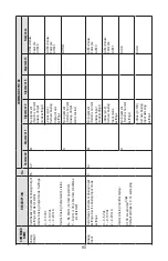
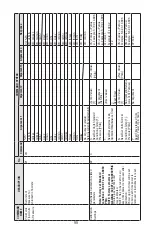
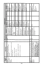
COMMAND
NAME
DESCRIPTION
No.
COMMAND SYNT
AX
Command
Argument 1
Argument 2
Argument 3
Argument 4
Response
ModBus **
Communication
settings and
address
(optional)
Sets/Reads instrument ModBus
Communication settings and address
(optional)**
Diagnostic Command (argument D) returns
following parameter:
MsgCtr –Message Counter
SRSErrCtr – CRC Error
SlaveMsgCtr – Slave Message Counter
ORErrCtr – Overrun Error Counter
35
MB
B
ModBus inter
face baud
rate parameter:1200
2400,4800,9600*,19200,
38400,57600,115200
No Argument (Return Current settings)
MBB:<Baud Rate V
alue>Example:
MBB:9600
<Baud Rate V
alue >
MBB:9600
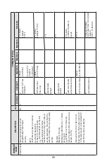
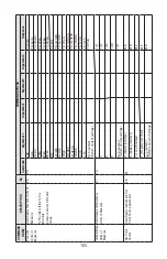
P ModBus inter
face Parity:
0 – None* 1 – ODD 2 – EVEN
No Argument (Return Current settings)
MBP:<Parity V
alue>
Example: MBP:0
<Parity V
alue >
MBP:0
S
ModBus inter
face Stop
Bits: [1 or 2*]
No Argument (Return Current settings)
MBS:<Stop Bits V
alue>
Example: MBS:2
<Stop Bit V
alue>
MBS:2
A
ModBus slave device
Address [1-247]
Factor
y default address:11
No Argument (Return Current settings
MBA:<Adress V
alue>
Example:MBA:11
<AddressV
alue>
MBA:11
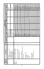
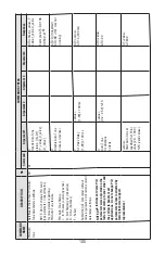
D Diagnostic of Modbus state machine communication counters
No Argument
(Return Current
settings
MBD: MgCtr
,SRSErrCtr
,
aveMsgCtr
,ORErrCtr
Example:MBD:1,0,0,0
R Reset ModBus communication Port and ModBus state machine.
No Argument
(Reports command
receiving)
MBR:Done
Read EEPROM Memor
y
Reads the value in the specifi
ed EEPROM
36
MR
0 to 413 (EEPROM Memor
y Index)
<memor
y value>
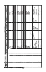
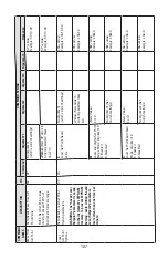
Write
EEPROM
Memor
y
Writes the specifi
ed value to the specifi
ed
memor
y location. W
ARNING: Use Carefully
,
can cause unit to malfunction.(Note: Some
addresses are write protected!)
W
ARNING: the instrument EEPROM
parameters were set on the factor
y to keep
best performance. Do not change
EEPROM parameters unless instructed by
factor
y technical support representative!
37
MW
115 to 413 (EEPROM
Memor
y Index) NOTE:
EEPROM indexes 0-114
are read only!
<V
alue>
Command:
MW
,XXX,<V
alue>
where: XXX= EEPROM
Index
Reply: Example:
MW
,101.3
Summary of Contents for DPC
Page 6: ...2...
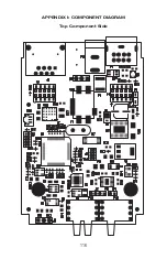
Page 120: ...116 APPENDIX I COMPONENT DIAGRAM Top Component Side...
Page 121: ...117 Bottom Component Side...

