


65
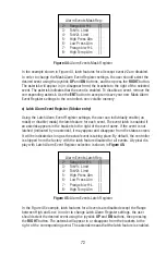
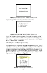
steps enabled (unmasked). A typical display with PSP Steps Mask selection is shown
in Figure 34 below.
PSP Steps Masc:
S01 0.0% 0s
[*]
S02 0.0% 10s
[*]
S03 25.0% 25s
[*]
S04 25.0% 1 0s
[*]
S05 50.0% 25s
[*]
S06 50.0% 10s
[*]
S07 25.0% 30s
[*]
Figure 34:
PSP Steps Mask Confi guration
In the example shown above, all PSP Steps are enabled. Each PSP Step assigned to
a corresponding bit in the PSP Steps Register. In order to change PSP Step mask
settings user should select desired Step using joystick
UP
or
DN
buttons and then
press
Joystick
RIGHT
button. The asterisk will appear/disappear on the right side of
the corresponding Step. The asterisk represents that Step is enabled. In order to
disable Step, the corresponding asterisk must be removed. Use joystick
ENT
button to
accept and save new PSP Steps mask settings in device non-volatile memory.
d) Program Set Point Steps Settings (Numerical Entry)
By using PSP Steps Settings menu selection the user can assign required set point
and time values for each step in the program. A typical display with PSP Steps
Settings selection is shown in Figure 35 below.
PSP Steps Settings:
S01 0.0% 0s [*]
S02 0.0% 10s [*]
S03 25.0% 25s [*]
S04 25.0% 10s [*]
S05 50.0% 25s [*]
S06 50.0% 10s [*]
S07 25.0% 30s [*]
Figure 35:
PSP Steps Settings
In the example shown above, Step 01 is selected. For each step there are two
parameters: set point value in %F.S. and time interval in seconds. In order to change
PSP Step settings user should select desired step using joystick
UP
and
DN
buttons
and then press the Joystick
ENT
button. The cursor in the selected (highlighted)
parameter will start fl ashing. Use
UP, DN
,
LEFT
, and
RIGHT
joystick buttons to adjust
desired value. Then press joystick
ENT
button to accept and save the new PSP Step
settings in the device’s non-volatile memory.
Summary of Contents for DPC
Page 6: ...2...
Page 120: ...116 APPENDIX I COMPONENT DIAGRAM Top Component Side...
Page 121: ...117 Bottom Component Side...


